Table of Contents
Advertisement
Quick Links
Installation and Operation Manual
This manual is available for free download on the distributor's web site. It is a copyrighted document. Re-sale is strictly
prohibited. The distributor may update this manual from time to time and cannot be responsible for problems, injuries,
or damages arising out of the use of information contained in any manual obtained from unauthorized sources.
CONTACT LOCAL BUILDING OR FIRE OFFICIALS ABOUT RESTRICTIONS AND INSTALLATION INSPECTION REQUIREMENTS IN LOCAL AREA.
READ THIS ENTIRE MANUAL BEFORE INSTALLATION AND USE OF THIS WOOD STOVE. FAILURE TO FOLLOW THESE
INSTRUCTIONS COULD RESULT IN PROPERTY DAMAGE, BODILY INJURY OR EVEN DEATH.
READ AND KEEP THIS MANUAL FOR REFERENCE
Printed in Canada
SAVANNAH
(DB03029 model)
Distributed by
My Fireplace Australia PTY Ltd
www.myfireplaceaustralia.com.au
20 Auto Way
Pakenham, Victoria 3810 AUSTRALIA
Phone: 03 59 415 008
Fax: 03 59 415 975
Email: info@myfireplaceaustralia.com.au
46238A
2021-01-28
Advertisement
Table of Contents

Related Manuals for Drolet DB03029


Summary of Contents for Drolet DB03029
- Page 1 Installation and Operation Manual SAVANNAH (DB03029 model) Distributed by My Fireplace Australia PTY Ltd www.myfireplaceaustralia.com.au 20 Auto Way Pakenham, Victoria 3810 AUSTRALIA Phone: 03 59 415 008 Fax: 03 59 415 975 Email: info@myfireplaceaustralia.com.au This manual is available for free download on the distributor’s web site. It is a copyrighted document. Re-sale is strictly prohibited.
- Page 3 THANK YOU FOR CHOOSING THIS WOOD FIRE. We want to congratulate you Please read this entire manual on your purchase and wish before you install and use your to help you get maximum new wood fire. Failure to follow If this wood fire is not satisfaction from your wood instructions may result in installed properly, heat...
-
Page 4: Table Of Contents
2.3 Zone Heating and How to Make it Work for You ..............11 2.4 The Benefits of Low Emissions and High Efficiency .............11 2.5 DROLET Commitment to You and the Environment .............11 2.5.1 What is Your New Wood fire Made Of? ..............11 Fuel .......................... - Page 5 4.5.6 Turning down the Air Supply ..................20 4.6 Building different fires for different needs ................20 4.6.1 Small Fires to Take the Chill Off the House ...............21 4.6.2 Long lasting Low Output Fires .................21 4.6.3 High Outpu Fires for Cold Weather ................21 4.6.4 Maximum Burn Cycle Times ..................21 4.6.5 North-South Fires Versus East-West Fires ..............22 Maintaining Your Wood Heating System ................
- Page 6 Appendix 3: OPTIONAL FIRE SCREEN INSTALLATION ............40 Appendix 4: AIR TUBES AND BAFFLE INSTALLATION ............41 Appendix 5: Exploded Diagram and Parts List ................. 43 DROLET Limited Lifetime Warranty ................... 48 Page 6 Installation and Operation Manual - Escape 1800...
-
Page 7: Part A - Operation And Maintenance
PART A - OPERATION AND MAINTENANCE Please see Part B for installation instructions. 1. Safery information • HOT WHILE IN OPERATION, KEEP CHILDREN, CLOTHING AND FURNITURE AWAY. CONTACT MAY CAUSE SKIN BURNS. GLOVES MAY BE NEEDED FOR WOOD FIRE OPERATION. •... -
Page 8: General Information
2. General Information 2.1 Specifications Model # Savannah (DB03029) Colour Metallic Black Combustible Hardwood Recommended heating area* 160 m Test Standard (safety) AS/NZS 2918 (2001) Test Standards (emissions) AS/NZS 4012/4013/4014.1 (2014) Optimum efficiency – hardwood Average efficiency – hardwood Average emissions – hardwood 1.2 g/kg... -
Page 9: Dimensions
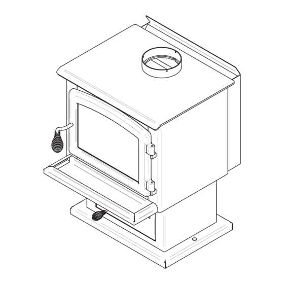
2.2 Dimensions Figure 1: Top view Figure 2: Front view Figure 3: Side view Installation and Operation Manual - Escape 1800 Page 9... -
Page 10: Combustion Chamber Dimensions
2.2.1 Combustion Chamber Dimensions Figure 4: Door opening Figure 5: Front view - Combustion chamber Figure 6: Front view - Combustion chamber Figure 7: Side view Page 10 Installation and Operation Manual - Escape 1800... -
Page 11: Zone Heating And How To Make It Work For You
2.5 Drolet’s Commitment to You and the Environment The Drolet team is committed to protecting the environment, so we do everything we can to use only materials in our products that will have no lasting negative impact on the environment. -
Page 12: Fuel
The baffle is made of vermiculite compressed with a binder to form a rigid board. Vermiculite can withstand temperatures above 2,000°F. It is not considered hazardous waste. Disposal at a waste management center is recommended. Firebrick is mainly composed of silicon dioxide, also known as silica, an earth derived product. It is most commonly found in nature in the form of sand and clay. -
Page 13: Log Length
3.2.3 Log Length Logs should be cut about 25 mm (1") shorter than the firebox so they fit in easily. Pieces that are slightly too long make loading the wood fire very difficult. The most common standard length of firewood is 400 mm (16"). The pieces should be a consistent length, with a maximum of 25 mm (1") variation from piece to piece. -
Page 14: How To Dry Firewood
3.2.5 How to dry firewood Firewood that is not dry enough to burn is the cause of most complaints about wood fires. The complaints usually involve a lack of heat and dirty door glass. Here are some facts to consider in estimating drying time: −... -
Page 15: Manufactured Logs
3.2.7 Compressed Wood Logs Do not burn manufactured logs made of wax impregnated sawdust or logs with any chemical additives. Manufactured logs made of 100% compressed sawdust can be burned, but use caution in the number of these logs burned at one time. -
Page 16: The Use Of A Fire Screen
The Use of a Fire Screen This stove has been tested for use with an open door in conjunction with a fire screen, sold separately. The fire screen must be properly secured on the stove to avoid any risk of sparks damaging the flooring. -
Page 17: Your First Fires
4.3 Your first fires Two things will happen as you burn your first few fires; the paint cures and the internal components of the wood fire are conditioned. As the paint cures, some of the chemicals vaporize. The vapors are not poisonous, but they do smell bad. -
Page 18: The Top Down Fire
4.4.2 The Top Down Fire The top down fire starting method solves two problems with the conventional method: first, it does not collapse and smother itself as it burns; and second, it is not necessary to build up the fire gradually because the firebox is loaded before the fire is lit. A top down fire can provide up to two hours of heating or more. -
Page 19: Ash Removal
Wood burns best in cycles. A cycle starts when a new load of wood is ignited by hot coals and ends when that load has been consumed down to a bed of charcoal about the same size as it was when the wood was loaded. Do not attempt to produce a steady heat output by placing a single log on the fire at regular intervals. -
Page 20: Firing Each New Load Hot
4.5.4 Firing Each New Load Hot Place the new load of wood on and behind the charcoal and not too close to the glass. Close the door and open the air control fully. Leave the air control fully open until the firebox is full of flames, the wood has charred to black and its edges are glowing red. -
Page 21: Small Fires To Take The Chill Off The House
4.6.1 Small Fires to Take the Chill Off the House To build a small fire that will produce a low heat output, use small pieces of firewood and load them crisscross in the firebox. The pieces should be only 75 mm to 100 mm in diameter. After raking the coals, you can lay two pieces parallel to each other corner to corner in the firebox and lay two more across them in the other direction. -
Page 22: North-South Fires Versus East-West Fires
Long burn times are not necessarily an indication of efficient wood fire operation. When you are home during the day and able to tend the fire, it is preferable to build a smaller fire that might provide three or four hours of heating than to fully load the firebox for a much longer burn. Shorter burn cycles make it easier to match the heat output of the wood fire to the heat demand of the space. -
Page 23: Glass Door
The deposits that form on the glass are the best indication of the quality of your fuel and how well you are doing in operating the wood fire. Your goal should be clear glass with no brown stains. If you continue to see brown stains on the glass, something about your fuel and operating procedure needs to be changed. -
Page 24: Replacing The Glass Gasket And/Or The Glass
5.2.3 Replacing the glass gasket and/or the glass It is a good idea to replace the glass gasket when the door gasket is replaced. The gasket is flat, adhesive-backed, woven fibreglass. Remove the screws (A) and glass retaining clips (B) then both glass frames (C) that hold the glass to the door frame (E). -
Page 25: Door
5.3 Door In order for the wood fire to burn at its best efficiency, the door must provide a perfect seal with the firebox. The tightness of the door seal can be verified by closing and latching the door on a strip of paper. The test must be performed all around the door. -
Page 26: Replacing The Door Gasket
5.3.2 Replacing the door gasket It is important to maintain the gasket in good condition. After a year or more of use, the door gasket will compress and become hard, which may allow air to leak past it. You can test the condition of the door gasket by closing and latching the door on a strip of paper. -
Page 27: Cleaning The Flue System
5.4.3 Cleaning the flue system Flue system cleaning can be a difficult and dangerous job. If you don’t have experience cleaning flue systems, you might want to hire a professional flue system sweep to clean and inspect the system for the first time. After having seen the cleaning process, you can decide if it is a job you would like to take on. -
Page 28: Part B - Installation
PART B - INSTALLATION It is very important to position the wood fire as close as possible to the flue system, and in an area that will favour the most efficient heat distribution possible throughout the house. The wood fire must therefore be installed in the room where the most time is spent, and in the most spacious room possible. -
Page 29: Regulations Covering Wood Fire Installation
6.2 Regulations Covering Wood fire Installation • IT IS RECOMMENDED THAT THE INSTALLATION OF YOUR DROLET WOOD FIRE BE CARRIED OUT BY A QUALIFIED SPECIALIST INSTALLER. IF ANY ELECTRICAL WORK IS REQUIRED, IT MUST BE CARRIED OUT BY A LICENSED ELECTRICIAN. -
Page 30: Clearances To Heat-Sensitive Materials
7. Clearances to Heat-Sensitive Materials It is of outmost importance that the clearances to heat-sensitive materials are carefully maintained upon the installation of the wood fire you have selected. Refer to the tables below. No part of the wood fire or flue pipe may be located closer to combustibles than the minimum clearance figures given. -
Page 31: Floor Protector
7.3 Floor Protector If the wood fire is to be installed on top of a combustible floor, it must be guarded by a non- combustible material as shown on the dotted line area of the above figures. Install a 1000 mm (Width) x 880 mm (Depth) floor protection of 9 mm of thickness with thermal conductivity of 0.1 m2 K/W per 9 mm thick. - Page 32 CONSTRUCTIONS AND CLEARANCE FACTORS FOR APPLIANCES HEAT SHIELDS WHICH ARE WITHIN 45 OF THE VERTICAL Minimum air gap Clearances HEAT SHIELD CONSTRUCTIONS dimensions (mm) factor Single layer of continuous material 0.40 Single layer of continuous material 0.30 Two spaced layers of continuous material 12+12 0.20 NOTES:...
-
Page 33: The Flue System
8. The Venting System 8.1 General The flue system made up of the flue system and the flue between the wood fire and the flue system, acts as the engine that drives your wood heating system. Even the best wood fire will not function safely and efficiently as intended if it is not connected to a suitable flue system. -
Page 34: Masonry Flue Systems
8.2.2 Masonry Flue System The wood fire may also be connected to a masonry flue system, provided the flue system complies with AS/NZS 2918 or with the construction rules found in the building code enforced locally. The flue system must have either a clay liner or a suitably listed stainless steel liner. -
Page 35: The Relationship Between The Flue System And The House
The top of the flue system should be tall enough to be above the air turbulence caused when wind blows against the house and its roof. The flue exit shall be located outside the building in which the appliance is installed so that: - The flue pipe shall extend not less than 4.6 m above the top of the floor protector;... -
Page 36: Why The Flue System Should Penetrate The Highest Heated Space
8.4.2 Why the Chimney Should Penetrate the Highest Heated Space When it is cold outside, the warm air in the house is buoyant so it tends to rise. This tendency of warm air to rise creates a slight pressure difference in the house. Called ‘stack effect’, it produces a slightly negative pressure low in the house (relative to outside) and a slightly positive pressure zone high in the house. - Page 37 Use 45 degrees elbows where possible, instead of 90 degrees elbows. The rules below are based on those found in the AS/NZS 2918:2001 installation code. Please carefully follow these installation instruction rules, or those enforced where you live. • Maximum overall length of the straight flue system: not less than 4.6 m above the top of the floor protector.
-
Page 38: Appendix 1: Installing The Optional Fresh Air Intake Kit Installation
APPENDIx 1: OPTIONAL FRESH AIR INTAKE KIT INSTALLATION This mobile home approved wood fire requires installation of a fresh air intake kit (A) and an insulated fresh air intake pipe (HVAC type, must meet ULC S110 or UL 181 class 0 or class 1) (B), sold separately. -
Page 39: Appendix 2: Optional Thermodisc Installation
APPENDIx 2: OPTIONAL THERMODISC INSTALLATION A thermodisc, sold separately, can be installed on the wood fire. Thermodisc allows the blower to operate only when the wood fire is hot enough. See the instructions provided with the thermodisc for more details. Screw the thermodisc (B) with the screws (C) supplied with the thermodisc on the back of the wood fire. -
Page 40: Appendix 3: Optional Fire Screen Installation
APPENDIx 3: OPTIONAL FIRE SCREEN INSTALLATION Open the door. Hold the fire screen by the two handles and bring it close to the door opening. Lean the upper part of the fire screen against the top door opening making sure to stove the top fire screen brackets behind the primary air deflector. -
Page 41: Appendix 4: Air Tubes And Baffle Installation
APPENDIx 4: AIR TUBES AND BAFFLE INSTALLATION Starting with the rear tube, lean and insert the right end of the secondary air tube into the rear right channel hole. Then lift and insert the left end of the tube into the rear left channel. Align the notch in the left end of the tube with the key of the left air channel hole. - Page 42 Note that secondary air tubes (B), (C) and (D) can be replaced without removing the baffle board (A). Important Notes The air tubes are identified for placement as follows: Front : 20 holes of 3.55 mm Middle : 30 holes of 3.80 mm Rear: 20 holes of 3.25 mm Page 42...
-
Page 43: Appendix 5: Exploded Diagram And Parts List
APPENDIx 5: ExPLODED DIAGRAM AND PARTS LIST Installation and Operation Manual - Escape 1800 Page 43... - Page 44 IMPORTANT: THIS IS DATED INFORMATION. When requesting service or replacement parts for your unit, please provide the model number and the serial number. We reserve the right to change parts due to technology upgrades or availability. Contact an authorized dealer to obtain any of these parts.
- Page 45 Item Description 44043 RHEOSTAT 240V (WITH NUT) 44087 RHEOSTAT NUT 44085 RHEOSTAT KNOB AC02056 QUICK CONNECT THERMODISC KIT 44046 THERMODISC F110-20F SE16059 ASH PLUG (CAST IRON) 29000 4" X 8" X 1 1/4" REFRACTORY BRICK 29015 4" X 9" X 1 1/4" REFRACTORY BRICK PL36062 4 1/2"...
-
Page 48: Drolet Limited Lifetime Warranty
20 Auto Way, Pakenham, Victoria 3810 ABN 98 167 605 843 WARRANTY DROLET WOOD HEATERS SOLD IN AUSTRALIA The warranty of the manufacturer (SBI - Stove Builder International Inc.) is supported and provided via My Fireplace Australia Pty Ltd (MFA). - Page 49 My Fireplace Australia Pty Ltd 20 Auto Way, Pakenham, Victoria 3810 ABN 98 167 605 843 5. Parts & Accessories are covered by a Back-to-Base Warranty. Parts and accessories are deemed to be those items that can be removed/replaced for normal maintenance: air tubes, bricks, baffles, gaskets, fans, handles, latches, hinges, and the like.
- Page 50 My Fireplace Australia Pty Ltd 20 Auto Way, Pakenham, Victoria 3810 ABN 98 167 605 843 Before shipping your heater or defective component to our warehouse, you must obtain an Authorization Number or expressed written approval/consent from your Distributor (MFA). Any merchandise shipped without authorisation will be refused automatically and returned to the sender.
- Page 52 Manufactured by: STOVE BUILDER INTERNATIONAL INC. 250, de Copenhague, Saint-Augustin-de-Desmaures (Quebec), Canada G3A 2H3 Tel: (418) 878-3040 Fax: (418) 878-3001 Distributed by: My fireplace Australia ACN 127 126 550 Fact.2, 5-7 Hogan Court PAKENHAM , VICTORIA, AUSTRALIA, 3810 Tel: (613) 59415 008 Fax: (613) 59415 975 www.myfireplaceaustralia.com.au...
Need help?
Do you have a question about the DB03029 and is the answer not in the manual?
Questions and answers