Table of Contents
Advertisement
Available languages
Available languages
Quick Links
Advertisement
Table of Contents

Summary of Contents for Telair ASP
- Page 1 GENERATORS DESCRIZIONE DEL PANNELLO DI CONTROLLO AUTOMATICO AUTOMATIC CONTROL PANEL DESCRIPTION DESCRIPTION DU PANNEAU DE CONTRÔLE AUTOMATIQUE BESCHRIJVING VAN HET AUTOMATISCHE BESCHREIBUNG DES AUTOMATISCHEN BEDIENPANELS DESCRIPCIÓN DEL PANEL DE CONTROL AUTOMÁTICO...
- Page 2 Automatic Starter Control Panel...
-
Page 3: Table Of Contents
DESCRIZIONE DEL PANNELLO DI CONTROLLO AUTOMATICO ..... 4 Collegamento Cavi ......................6 AUTOMATIC CONTROL PANEL DESCRIPTION ......... 8 Cable Connection......................10 DESCRIPTION DU PANNEAU DE CONTRÔLE AUTOMATIQUE....12 Connexion Câbles ......................14 BESCHRIJVING VAN HET AUTOMATISCHE ..........16 Aansluiting van de Kabels ....................18 BESCHREIBUNG DES AUTOMATISCHEN BEDIENPANELS.... -
Page 4: Descrizione Del Pannello Di Controllo Automatico
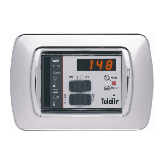
DESCRIZIONE DEL PANNELLO DI CONTROLLO AUTOMATICO Gli elementi che lo compongono sono: 1 Interruttore ON/OFF per la funzione di accensione e spegnimento 2 Interruttore AUTO/MAN per la funzione di automatico o manuale 3 Display 4 Pulsante commutatore orario o voltmetrico 5 Reset 6 Segnalatore di generatore funzionante (lampeggiante) 7 Segnalatore di funzione automatica... - Page 5 Funzionamento AUTOMATICO Posizionare l’interruttore AUTO/MAN (2) in posizione AUTO e poi posizionare l’interruttore di accensione (1) in posizione ON. Si illuminerà il segnalatore di funzione automatica (7) e se la batteria con cui è alimentato il generatore ha una tensione superiore a 11,5 volt si illuminerà il segnalatore di batteria carica (11).
-
Page 6: Collegamento Cavi
Collegamento Cavi... -
Page 8: Automatic Control Panel Description
AUTOMATIC CONTROL PANEL DESCRIPTION The elements making them up are: ON/OFF switch for the start-up and switch-off function AUTO/MAN switch for the automatic or manual function Display Hour or voltmetric switch button Reset Generator running indicator (flashing) Automatic function indicator Startup failed indicator Maintenance request indicator Fuel reserve indicator... - Page 9 AUTOMATIC operation Position the AUTO/MAN (2) switch on the AUTO position and set the startup switch (1) to ON position. The automatic function indicator (7) will light up. If the battery which supplies the generating set has a voltage of more than 11.5 Volts, the battery charged indicator (11) will light up.
-
Page 10: Cable Connection
Cable Connection... -
Page 12: Description Du Panneau De Contrôle Automatique
DESCRIPTION DU PANNEAU DE CONTRÔLE AUTOMATIQUE Il se compose des parties suivantes: Interrupteur MARCHE/ARRÊT de mise sous et hors tension Interrupteur AUTO/MAN pour le fonctionnement Automatique ou Manuel Affichage Bouton-poussoir de commutation horaire ou voltmétrique R.A.Z. Voyant générateur en marche (clignotant) Voyant fonctionnement automatique Voyant démarrage non réussi Voyant rappel de maintenance... - Page 13 Fonctionnement AUTOMATIQUE Positionner le disjoncteur AUTO/MAN (2) sur AUTO et l'interrupteur de mise sous tension (1) sur ON. Le voyant de fonctionnement automatique s'allume (7) et, si la tension de la batterie d'alimentation du générateur est supérieure à 11,5 Volts, le voyant de batterie chargée s'allume (11).
-
Page 14: Connexion Câbles
Connexion Câbles... -
Page 16: Beschrijving Van Het Automatische
BESCHRIJVING VAN HET AUTOMATISCHE Het paneel bestaat uit de volgende onderdelen: 1 ON/OFF schakelaar voor de in- en uitschakelfunctie 2 AUTO/MAN schakelaar voor de automatische of handbediende werkingsfunctie 3 Display 4 Omschakelknop tijd of voltmeter 5 Reset 6 Indicatielampje “generator in werking” (knippert) 7 Indicatielampje “automatische werkingsfunctie”... - Page 17 Automatische werking Zet de AUTO/MAN schakelaar (2) op de stand AUTO en zet de ON/OFF schakelaar (1) daarna op de stand ON. Het indicatielampje “automatische werkingsfunctie” (7) zal gaan branden en als de accu waarmee de generator van stroom voorzien wordt een hogere spanning heeft dan 11,5 Volt zal het indicatielampje “accu geladen”...
-
Page 18: Aansluiting Van De Kabels
Aansluiting van de Kabels... -
Page 20: Beschreibung Des Automatischen Bedienpanels
BESCHREIBUNG DES AUTOMATISCHEN BEDIENPANELS Das Bedienpanel umfasst die folgenden Elemente: ON/OFF-Schalter für das Ein- und Ausschalten AUTO/MAN Schalter für Automatik oder manuellen Betrieb Display Umschalttaste: Uhr oder Spannungsmesser Reset Anzeige: Stromerzeuger in Betrieb (blinkend) Anzeige: Automatik Anzeige: Inbetriebnahme gescheitert Anzeige: Wartungsaufruf Anzeige: Gasreserve Anzeige: Batterie geladen Anzeige: min. - Page 21 AUTOMATISCHER Betrieb Den AUTO/MAN-Schalter (2) in AUTO-Schaltstellung und danach den Ein-Schalter (1) auf ON stellen. Es leuchtet die Automatik-Anzeige (7) auf. Falls die Spannung der Batterie, mit der der Stromerzeuger versorgt wird, höher als 11,5 Volt ist, leuchtet die Anzeige für Batterie geladen (11) auf.
-
Page 22: Anschluss Der Kabel
Anschluss der Kabel... -
Page 24: Descripción Del Panel De Control Automático
DESCRIPCIÓN DEL PANEL DE CONTROL AUTOMÁTICO Los elementos que lo componen son: 1 Interruptor ON/OFF para la función de encendido y apagado 2 Interruptor AUTO/MAN para la función de automático o manual 3 Display 4 Pulsador conmutador horario o voltímetro 5 Reset 6 Señalizador de generador en funcionamiento (parpadeante) 7 Señalizador de función automática... - Page 25 Funcionamiento AUTOMÁTICO Colocar el interruptor AUTO/MAN (2) en posición AUTO y después colocar el interruptor de encendido (1) en posición ON. Se iluminará el señalizador de función automática (7) y si la batería con la que está alimentado el generador tiene una tensión superior a 11,5 voltios se iluminará...
-
Page 26: Conexión Cables
Conexión Cables... - Page 28 18700 Aubigny sur Nere - France E-mail: info@telecogroup.com Tel.02 48580367 – Fax 02 48583585 www.telecogroup.com e-mail: teleco.telair@bleysetd.com Service Technique France : 06 83 31 44 05 ESPAÑA - NAUCCA CARAVANING, S.A. Poligono Industrial CAN ROQUETA 2 – Calle Can Lletget,2 08202 Sabadell (Barcelona) - España...
Need help?
Do you have a question about the ASP and is the answer not in the manual?
Questions and answers