Table of Contents
Advertisement
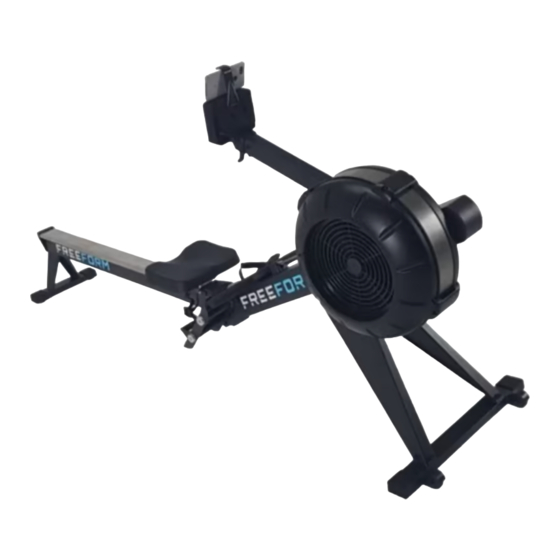
FREEFORM
R2000 AIR ROWER
Product May Vary Slightly From Pictured.
CAUTION:
Weight on this product should not exceed 297 lbs/135 kgs.
Owner's
Manual
WARNING
!
Exercise can present a
h e a l t h r i s k . C o n s u l t a
physician before beginning
any exercise program with
this equipment. If you feel
faint or dizzy, immediately
d i s c o n t i n u e u s e o f t h i s
equipment. Serious bodily
i n j u r y c a n o c c u r i f t h i s
equipment is not assembled
and used correctly. Serious
bodily injury can also occur
if all instructions are not
followed. Keep others and
pets away from equipment
when in use. Always make
sure all bolts and nuts are
securely tightened prior to
each use. Follow all safety
instructions in this manual.
When calling for parts or
service, please specify
the following number :
Model#: R2000
Advertisement
Table of Contents

Related Manuals for Stamina FREEFORM R2000 AIR ROWER


Summary of Contents for Stamina FREEFORM R2000 AIR ROWER
- Page 1 FREEFORM Owner's R2000 AIR ROWER Manual WARNING Exercise can present a h e a l t h r i s k . C o n s u l t a physician before beginning any exercise program with this equipment. If you feel faint or dizzy, immediately d i s c o n t i n u e u s e o f t h i s equipment.
-
Page 2: Safety Instructions
TABLE OF CONTENTS SAFETY INSTRUCTIONS WARNING Cancer and Reproductive Harm www.P65Warnings.ca.gov WARNING C nsult your physician before starting this or any exercise program. This is especially important if you are over the age of 35, have never exercised before, only. Do not use in institutional or commercial applications. Failure to follow all warnings and instructions could result in serious injury or death. -
Page 3: Before You Begin
BEFORE YOU BEGIN Thank you for choosing the R2000 AIR ROWER. We take great pride in producing this quality product and hope it will provide many hours of quality exercise to make you feel better, look better, and enjoy life to its fullest. It's a proven fact that a regular exercise program can improve your physical and mental health. -
Page 4: Equipment Warning, Caution & Notice Labels
EQUIPMENT WARNING, CAUTION & NOTICE LABELS This chart is provided to help identify the warning, caution, and notice labels on the R2000 AIR ROWER. Please take a moment to familiarize yourself with all of the warning, caution, and notice labels. Label is larger than actual size CAUTION LABEL(115) -
Page 5: Hardware Identification Chart
HARDWARE IDENTIFICATION CHART This chart is provided to help identify the fasteners used in the assembly process. Place the washers or the ends of the bolts or screws on the circles to check for the correct diameter. Use the small scale to check the length of the bolts and screws. - Page 6 ASSEMBLY INSTRUCTIONS STEP 1 Refer to illustration 1. Turn the main assembly of the R2000 AIR ROWER upside down and place it in the packing material styrofoam(A) and (B) to avoid breaking the chain covers. Attach the LEFT and RIGHT SUPPORT LEGS(7, 8) to the MAIN FRAME(1) with SOCKET HEAD BOLTS(M8x1.25x12mm) (81) and WASHERS(M8)(79).
- Page 7 ASSEMBLY INSTRUCTIONS STEP 3 Refer to illustration 3. Lift up the MAIN FRAME(1) and RAIL FRAME(2) to insert the RAIL FRAME(2) into the MAIN FRAME(1). Make the SHAFT(24) on the MAIN FRAME(1) fit into the gap in the RAIL FRAME(2). Then put the MAIN FRAME(1) and RAIL FRAME(2) down.
- Page 8 ASSEMBLY INSTRUCTIONS STEP 5 There is an “L” decal on the left PEDAL CAP(45L), and an “R” decal on the right PEDAL CAP(45R). Attach the right PEDAL CAP ASSEMBLY(45R) to the right side of the MAIN FRAME(1) with SOCKET HEAD BOLTS(M8x1.25x150mm)(84) and SECURING CAPS(9). Repeat on other side.
- Page 9 ASSEMBLY INSTRUCTIONS STEP 6 Refer to the detail view. Insert the CELL PHONE BRACKET(20) into the slot in the COMPUTER(19). Hang the RUBBER BAND(21) onto the CELL PHONE BRACKET(20) and the COMPUTER(19) as shown. STEP 7 Install two size C batteries into the COMPUTER(19), the batteries are not included. See page 18 for detailed battery installation instructions.
-
Page 10: Computer Instructions
COMPUTER INSTRUCTIONS Your R2000 AIR ROWER utilizes an air fan system to create resistance for your workout. We recommend that you use this computer console to vary your workout from session to session and note your important source of motivation and interest which will help keep you on track. POWER ON: andlebar or press any button. - Page 11 COMPUTER INSTRUCTIONS STROKES/FREQ.MIN TIME DISTANCE/CYCLE Matrix Display HEART RATE CALORIES WATTS PADDLE WIDTH LCD DISPLAY INSTRUCTIONS DISTANCE/ "500" for presetting the distance for preset DISTANCE Program, from CYCLE 500 to 9999 meters, and counts down from the preset value. Displays the distance you are traveling during exercise, from 1 meter up to 9999 meters. “8”...
-
Page 12: Program Descriptions
COMPUTER INSTRUCTIONS PROGRAM DESCRIPTIONS This computer contains the programs, Normal Program, Distance, Time, Calories, Game, 20/10 Interval Program, 10/20 Interval Program, and 10/10 User Setting Interval Program. Refer to the following for the operation of these programs. 1. NORMAL PROGRAM: You can pull on the HANDLEBAR(3) to power on the computer and exercise with this program directly. - Page 13 COMPUTER INSTRUCTIONS NOTE: To exercise with the following programs, you will not be able to preset the function values. Refer to the following for the operation of these programs. We call this program Score Game, use SELECT button to 5. GAME PROGRAM: select the program.
-
Page 14: Operation Descriptions
COMPUTER INSTRUCTIONS This program will allow the user to manually preset the workout 8. 10/10 USER SETTING INTERVAL PROGRAM: time and rest time from 10 to 99 seconds. The user will exercise for the preset workout time, then rest for the preset rest time, and will cycle this way. -
Page 15: Operational Instructions
OPERATIONAL INSTRUCTIONS Indicator LOAD ADJUSTMENT There is a DAMPER(42) built into the RIGHT FAN CAGE(43). Move the Indicator in the DAMPER(42) to point to the numbers on the RIGHT FAN CAGE(43) to adjust the load. There are settings from 1 to 9. Setting #1 will provide the lowest resistance. Setting #9 will provide the highest resistance. -
Page 16: Maintenance
OPERATIONAL INSTRUCTIONS USING THE CELL PHONE BRACKET The CELL PHONE BRACKET(20) can move up and down. Move up the CELL PHONE BRACKET(20), then slide the Cell Phone into the gap between the CELL PHONE BRACKET(20) and the COMPUTER(19). Move down the CELL PHONE BRACKET(20) to clip the Cell Phone in position. Cell Phone MAINTENANCE The safety and integrity designed into the R2000 AIR ROWER can only be maintained when... - Page 17 STORAGE 1. To store the R2000 AIR ROWER , simply keep it in a clean dry place. 2. To avoid damage to the electronics, remove the batteries from the COMPUTER(19) before storing the R2000 AIR ROWER for one year or more. 3.
-
Page 18: Conditioning Guidelines
CONDITIONING GUIDELINES How you begin your exercise program depends on your physical condition. If you have been inactive for several years or are severely overweight, start slowly and increase your workout time gradually. Increase your workout intensity gradually by monitoring your heart rate while you exercise. Remember to follow these essentials: Have your doctor review your training and diet programs. -
Page 19: Warm-Up And Cool-Down
WARM-UP and COOL-DOWN Warm-Up The purpose of warming up is to prepare your body for exercise and to minimize injuries. Warm up for two to five minutes before strength training or aerobic exercising. Perform activities that raise your heart rate and warm the working muscles. Activities may include brisk walking, jogging, jumping jacks, jump rope, and running in place. -
Page 20: Product Parts Drawing
PRODUCT PARTS DRAWING FRONT BACK... -
Page 21: Parts List
PARTS LIST PART# PART NAME Main Frame Rail Frame Handlebar Front Stabilizer Pedal Support Computer Post Left Support Leg Right Support Leg Securing Cap Seat Carriage Bungee Cord Hook Chain Idler Bracket Rail Outlet Perforation Spacer (ø8.2 x ø12 x 3.2mm) Long Spacer (ø8.2 x ø12 x 71.6mm) Chain Roller Spacer (ø6.2 x ø10 x 15.5mm) Computer... - Page 22 PARTS LIST PART# PART NAME Guide Roller Seat Roller Roller Sleeve Moving Wheel Rail Cap Main Frame Cap Mounting Cap Bottom Cover Plastic Washer (ø10.2 x ø14 x 1mm thick) Bolt, Round Head (M6 x 1 x 10mm) Lock Washer, Internal Tooth (M6) Nylock Nut (M6 x 1) Screw, Round Head (ST4.2 x 10mm) Washer (M6)
Need help?
Do you have a question about the FREEFORM R2000 AIR ROWER and is the answer not in the manual?
Questions and answers