Table of Contents
Advertisement
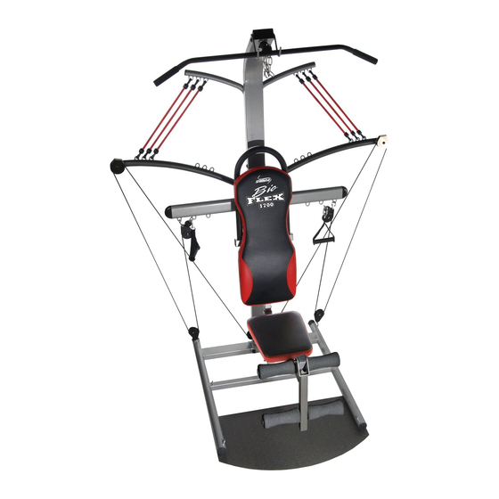
Owner's Manual
Product May Vary Slightly From Pictured.
CAUTION:
Weight on this product should not exceed 250 lbs.
This Product is Produced Exclusively by
2040 N. Alliance, Springfield, MO 65803
Customer Service
1 (800) 375-7520
www.staminaproducts.com
WARNING
!
Exercise can present a
h e a l t h r i s k . C o n s u l t a
physician before beginning
any exercise program with
this equipment. If you feel
faint or dizzy, immediately
d i s c o n t i n u e u s e o f t h i s
equipment. Serious bodily
i n j u r y c a n o c c u r i f t h i s
equipment is not assembled
and used correctly. Serious
bodily injury can also occur
if all instructions are not
followed. Keep others and
pets away from equipment
when in use. Always make
sure all bolts and nuts are
securely tightened prior to
each use. Follow all safety
instructions in this manual.
When calling for parts or
service, please specify
the following number :
Model#: 50-0170
STAMINA PRODUCTS
MADE IN CHINA
©
2009 Stamina Products, Inc.
2009, 09
!
Advertisement
Table of Contents

Subscribe to Our Youtube Channel
Related Manuals for Stamina BioFLEX 1700


Summary of Contents for Stamina BioFLEX 1700
- Page 1 CAUTION: Weight on this product should not exceed 250 lbs. This Product is Produced Exclusively by STAMINA PRODUCTS MADE IN CHINA 2040 N. Alliance, Springfield, MO 65803 Customer Service © 2009 Stamina Products, Inc. 1 (800) 375-7520 2009, 09 www.staminaproducts.com...
-
Page 2: Table Of Contents
21. The BioFLEX 1700 should be used by only one person at a time. 22. The BioFLEX 1700 is for consumer use only. It is not for use in public or semipublic facilities. WARNING: Before starting any exercise or conditioning program you should consult with your personal physician to see if you require a complete physical exam. -
Page 3: Customer Service
THANK YOU FOR PURCHASING THE BioFLEX 1700 Your BioFLEX 1700 does require assembly. Please follow the assembly steps set forth in this manual. With regular workouts, you will be getting your body into shape and be on your way to achieving a happier and healthier lifestyle. -
Page 4: Before You Begin
BEFORE YOU BEGIN Thank you for choosing the BioFLEX 1700. We Although Stamina constructs its products with the finest materials and uses the highest standards take great pride in producing this quality product and hope it will provide many hours of quality... -
Page 5: Equipment Warning & Notice Labels
EQUIPMENT WARNING & NOTICE LABELS This chart is provided to help identify the warning & notice labels on the BioFLEX 1700. Please take a moment to familiarize yourself with all of the warning & notice labels. Label is larger than actual size... -
Page 6: Hardware Identification Chart
HARDWARE IDENTIFICATION CHART This chart is provided to help identify the hardware used in the assembly process. Place the washers or the ends of the bolts or screws on the circles to check for the correct diameter. Use the small scale to check the length of the bolts and screws. -
Page 7: Assembly Instructions
ASSEMBLY INSTRUCTIONS Place all parts from the box in a cleared area and position them on the floor in front of you. Remove all packing materials from your area and place them back into the box. Do not dispose of the packing materials until assembly is completed. - Page 8 ASSEMBLY INSTRUCTIONS STEP 4 Attach the TOP BEAM(5) to the UPRIGHT(4) with BUTTON HEAD BOLTS(M10x1.5x15mm)(60) and WASHERS(M10)(70). STEP 5 Attach the CROSSING BAR(7) and FRONT SUPPORT(6) to the UPRIGHT(4) with BUTTON HEAD BOLTS(M10x1.5x110mm)(65), WASHERS(M10)(70), NYLOCK NUTS(M10x1.5)(68), LOCK WASHERS(M10)(71), and BUTTON HEAD BOLTS(M10x1.5x60mm)(62). Do not tighten the bolts. STEP 6 Attach the FRONT SUPPORT(6) to the BASE FRAME(1) with BUTTON HEAD BOLTS(M10x1.5x15mm) (60) and WASHERS(M10)(70).
- Page 9 ASSEMBLY INSTRUCTIONS STEP 7 Attach the TENSION POSTS(8) to the back of the TOP BEAM(5) with BUTTON HEAD BOLTS (M10x1.5x50mm)(61), LOCK WASHERS(M10)(71) and WASHERS(M10)(70). STEP 8 Slide the LEFT and RIGHT FORCE ARMS(9, 10) onto the shafts on UPRIGHT(4) and secure with WASHERS(M10)(70) and NYLOCK NUTS(M10x1.5)(68).
- Page 10 ASSEMBLY INSTRUCTIONS STEP 10 Attach the HANDRAIL(20) to the FRONT SUPPORT(6) with BUTTON HEAD BOLTS(M8x1.25x15mm) (55) and WASHERS(M8)(69). STEP 11 NOTE: Do not over tighten BOLTS(56, 59) as PULLEYS(23) must rotate freely after BOLTS(56, 59) are tightened. Run the Eyelet End of the LAT BAR CABLE(25), 2050mm (80.7”) long, through the slot at the top end of the TOP BEAM(5).
- Page 11 ASSEMBLY INSTRUCTIONS STEP 12 Hook a PULLEY SET(29) to one of the hooks on the end of the CROSSING BAR(7). Run the Eyelet End of the CABLE(28), 3980mm (156.7”) long, through the PULLEY SET(29). Run the Eyelet End of the CABLE(28) through another PULLEY SET(29). Hook the PULLEY SET(29) to the hook on the BASE FRAME(1).
- Page 12 ASSEMBLY INSTRUCTIONS STEP 13 Hook the SEAT FRAME(11) onto one of the Lugs on the FRONT SUPPORT(6) and secure with the LOCKING KNOB(16) and WASHER(M10)(70). NOTE: The three Lugs on the FRONT SUPPORT(6) allow the SEAT FRAME(11) to be attached in three different positions.
- Page 13 ASSEMBLY INSTRUCTIONS STEP 16 Attach the LEG LIFT(12) to the SEAT FRAME(11) with BUTTON HEAD BOLT(M10x1.5x65mm)(63), WASHERS(M10)(70), and NYLOCK NUT(M10x1.5)(68). Do not over tighten the bolt, as the LEG LIFT(12) must be able to pivot smoothly. STEP 17 Slide a FOAM PAD(15) onto one end of the PAD TUBE(14). Press a ROUND PLUG(44) into the end with the FOAM PAD(15) of the PAD TUBE(14).
-
Page 14: Setting Up The Accessories
SETTING UP THE ACCESSORIES LAT BAR(36) Attach the LAT BAR(36) to the LAT BAR CABLE(25), with the warning label to the front, with a QUICK LINK(39). Then store the LAT BAR(36) in the hooks provided on the TOP BEAM(5). For some exercises, the CHAIN(41) should be attached between the LAT BAR(36) and the LAT BAR CABLE(25) with two QUICK LINKS(39). -
Page 15: Conditioning Guidelines
CONDITIONING GUIDELINES How you begin your exercise program depends on your physical condition. If you have been inactive for several years or are severely overweight, start slowly and increase your workout time gradually. Increase your workout intensity gradually by monitoring your heart rate while you exercise. Remember to follow these essentials: Have your doctor review your training and diet programs. -
Page 16: Warm-Up And Cool-Down
WARM-UP and COOL-DOWN Warm-Up The purpose of warming up is to prepare your body for exercise and to minimize injuries. Warm up for two to five minutes before strength training or aerobic exercising. Perform activities that raise your heart rate and warm the working muscles. Activities may include brisk walking, jogging, jumping jacks, jump rope, and running in place Stretching while your muscles are warm after a proper warm-up and again after your Stretching... -
Page 17: Operational Instructions
OPERATIONAL INSTRUCTIONS BioFLEX 1700 RESISTANCE DIAGRAM 1 2 3 A B C BioFLEX 1700 RESISTANCE CHART The BioFLEX™ cable system provides user defined workout movements while utilizing lower amounts of resistance to simulate actions performed in everyday activities. All resistances below are approximate and measured in pounds. -
Page 18: Training Tips & Workout Instructions
TRAINING TIPS 1. Always warm up for at least 5 minutes before doing resistance training. 2. On your first set of exercises, keep the resistance light. 3. Stretching is recommended after the warm up or at the end of the workout. 4. -
Page 19: Workout Instructions
WORKOUT INSTRUCTIONS Calf Raises Single Leg Kick Back Standing Hip Abduction Standing Hip Adduction Seated Ankle Eversion Seated Ankle Inversion Seated Chest Press Incline Chest Press... - Page 20 WORKOUT INSTRUCTIONS Chest Fly Lat Bar Pulldown SIngle Arm Pulldown Standing Row Standing Straight Arm Pulldown Seated Shoulder Press Shoulder Shrugs Upright Row...
- Page 21 WORKOUT INSTRUCTIONS Seated Front Raise Seated Lateral Raise Rotator Cuff-Low External Rotation Rotator Cuff-Internal Rotation Rotator Cuff-High External Rotation Standing Biceps Curl Seated Wrist Curl Standing Triceps Pushdown...
- Page 22 WORKOUT INSTRUCTIONS Reverse Grip Triceps Pushdown Single Arm Triceps Pushdown Single Arm Triceps Kickback Ab Crunch Oblique Crunch Standing Trunk Rotation Side Bend...
-
Page 23: Storage & Maintenance
1. To store the BioFLEX 1700, simply keep it in a clean dry place. 2. To move the BioFLEX 1700, hold the upright of the BioFLEX 1700 while you tip it backward. When the WHEELS(32) come in contact with the floor you can easily roll the BioFLEX 1700. -
Page 24: Product Parts Drawing
PRODUCT PARTS DRAWING BACK FRONT... -
Page 25: Parts List
PARTS LIST PART# PART NAME Base Frame Base Plate Lower Upright Upright Top Beam Front Support Crossing Bar Tension Post Left Force Arm Right Force Arm Seat Frame Leg Lift Leg Lift Bushing Pad Tube Foam Pad Locking Knob Mounting Plate Seat Back Cushion Handrail... - Page 26 PARTS LIST PART# PART NAME Round Plug (50.8mm) Square Plug (38mm) / for 1.5 thick tube Square Plug (38mm) / for 2.0 thick tube Rectangular Plug (50mm x 100mm) Bolt, Round Head (M6 x 1 x 15mm) Bolt, Flat Head (M8 x 1.25 x 20mm) Bolt, Flat Head (M8 x 1.25 x 50mm) Bolt, Button Head (M8 x 1.25 x 15mm) Bolt, Button Head (M8 x 1.25 x 45mm)
-
Page 27: Warranty
To implement this limited warranty, send a written notice stating your name, date, and place of purchase and a brief description of the defect along with your receipt to Stamina Products, Inc. P.O. Box 1071, Springfield Missouri, USA, 65801-1071, or email us at customerservice@staminaproducts.com, or call us at 1-800-375-7520. -
Page 28: Notes
NOTES... - Page 29 NOTES...
-
Page 30: Fax/Mail Ordering Form
TELEPHONE ONLINE MAIL CUSTOMER SERVICE CUSTOMER SERVICE CUSTOMER SERVICE STAMINA PRODUCTS, INC. Tel: 1 (800) 375-7520 Fax: (417) 889-8064 customerservice@staminaproducts.com ATTN: Customer Service www.staminaproducts.com P.O. Box 1071 Springfield, MO. 65801-1071 Detach and Mail or Fax the Form Below Stamina Products, Inc.
Need help?
Do you have a question about the BioFLEX 1700 and is the answer not in the manual?
Questions and answers
I need to order Tension Cord (12x440mm) with/ Hooks