Key Automation RAY Instructions And Warnings
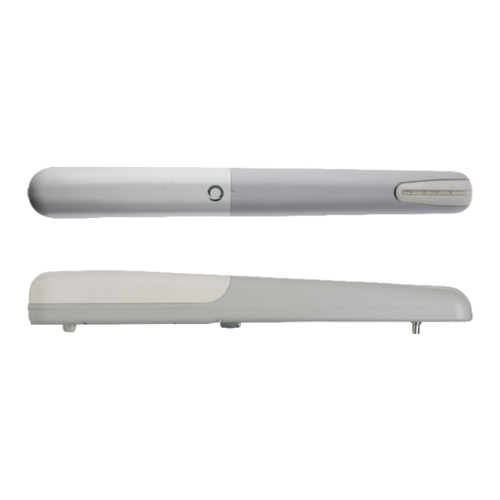
Gear motor for hinged gates
Hide thumbs
Also See for RAY:
- Instructions and warnings for installation and use (52 pages) ,
- Instructions and warnings (44 pages) ,
- Instructions and warnings (20 pages)
Table of Contents
Advertisement
Available languages
Available languages
Quick Links
Advertisement
Chapters
Table of Contents

Related Manuals for Key Automation RAY


Summary of Contents for Key Automation RAY
- Page 1 Motoriduttore per cancelli a battente Gear motor for hinged gates Antriebe für Drehtore Motorreductor para cancelas batientes Motoréducteur pour portails à battants Motorredutores para portões de batente Motoreduktor do bram skrzydłowych...
-
Page 2: Table Of Contents
INDICE Avvertenze per la sicurezza pag. 3 Introduzione al prodotto pag. 4 Descrizione del prodotto pag. 4 Modello e caratteristiche tecniche pag. 4 Verifiche preliminari pag. 4 Installazione del prodotto pag. 5 Installazione pag. 5 Installazione staffa di fissaggio posteriore con pag. - Page 3 KEY AUTOMATION si riserva il diritto di modificare le presenti se il cavo di alimentazione risulta danneggiato esso deve essere istruzioni qualora necessario, queste e/o versione superiore si...
-
Page 4: Introduzione Al Prodotto
E’ vietato l’utilizzo dei motoriduttori per applicazioni differenti da I motoriduttori RAY sono progettati e costruiti per il montaggio su quelle sopra indicate. ante battenti nei limiti di peso riportati nella tabella delle specifiche 2.2 - Modello e caratteristiche tecniche... -
Page 5: Installazione Del Prodotto
4 - INSTALLAZIONE DEL PRODOTTO 4.1 - Installazione Prima di procedere con l’installazione, verificare l’integrità del pro- ATTENZIONE ! dotto e che tutti i componenti siano presenti nella confezione (Fig.3). Verificare inoltre che la zona di fissaggio del motoriduttore sia com- L’installatore deve verificare che il range di temperature ripor- patibile con le dimensioni di ingombro (Fig.1). -
Page 6: Installazione Del Motoriduttore
4.6 - Installazione del motoriduttore Aprire lo sportello di sblocco e svitare le n. 2 viti che fissano il coper- fissaggio (Fig.9B). chio posteriore (Fig. 9A). Inserire il perno della staffa di scorrimento nella boccola della staffa Togliere il coperchio superiore facendolo prima scorrere leggermen- anteriore e fissarlo tramite la vite e la rondella in dotazione (Fig.9C). - Page 7 INDEX Safety warnings p. 9 Product overview p. 10 Product description p. 10 Models and characteristics p. 10 Preliminary checks p. 10 Installing the product p. 11 Installation p. 11 Installing the rear fixing bracket with inward p. 11 opening Installing the front fixing bracket with inward p.
- Page 8 During installation ensure that no liquids are able to available at www.keyautomation.it enter the various devices; should this occur, disconnect the power supply immediately and contact a Key Automation Service Centre. Use of the automation system in these conditions may cause hazards;...
- Page 9 2 - PRODUCT OVERVIEW 2.1 - Description of the product specifications table. RAY gear motors are destined to be installed in systems for the automation of gates with hinged doors. The use of gear motors for applications which differ from those RAY gear motors have been designed and constructed to be fitted indicated above is prohibited.
- Page 10 4 - PRODUCT INSTALLATION 4.1 - Installation Before proceeding with the installation, check the integrity of the ATTENTION ! product and that all components are present in the package (Fig. 3). Also make sure that the mounting area of the gear motor is The installer must verify that the working temperature range Also check that the gearmotor’s installation zone is compatible with stated on the automation device is suitable for the location...
- Page 11 4.6 - Installing the gear motor Open the release door and remove the 2 screws that secure the rear Insert the pin of the sliding bracket into the bush of the front bracket cover (Fig. 9A). and secure it with the screw and washer provided (Fig.9C). Remove the top cover first sliding it slightly backward (Fig.
- Page 12 INHALTSVERZEICHNIS Sicherheitshinweise S. 15 Produkteinführung S. 16 Produktbeschreibung S. 16 Modell und technische Merkmale S. 16 Vorabkontrollen S. 16 Produktinstallation S. 17 Installation S. 17 Installation des hinteren Befestigungsbügels S. 17 mit Öffnung nach innen Installation des vorderen Befestigungsbügels S. 17 mit Öffnung nach innen Installation des hinteren Befestigungsbügels S.
-
Page 13: Sicherheitshinweise
Die einzelnen Komponenten der Automatisierung dürfen nicht in den. Wasser oder andere Flüssigkeiten getaucht werden. Bei der In- KEY AUTOMATION behält sich vor, diese Anweisungen notfalls stallation darauf achten, dass keine Flüssigkeit ins Innere der Vor- zu ändern; diese Anweisungen und/oder eine neuere Version richtungen dringt. -
Page 14: Produkteinführung
2 - PRODUKTEINFÜHRUNG 2.1 - Produktbeschreibung Gewichtsgrenzen entworfen und gebaut. Die Antriebe RAY sind für den Einbau in Automationsanlagen für Toren mit Drehflügeln bestimmt. Die Verwendung der Getriebemotoren für andere Anwendungen Die Antriebe RAY werden zur Montage an Drehflügeln innerhalb der als den oben angegebenen ist verboten. -
Page 15: Produktinstallation
4 - PRODUKTINSTALLATION 4.1 - Installation Prüfen Sie vor dem Einbau die Unversehrtheit des Produktes sowie ACHTUNG ! ob alle Bauteile in der Packung vorhanden sind (Abb. 3). Außerdem ist zu prüfen, dass die Befestigungszone des Getriebe- Der Installateur muss prüfen, dass der auf dem Antrieb ange- motors mit den Ausmaßen verträglich ist (Abb.1). -
Page 16: Installation Des Getriebemotors
4.6 - Installation des Getriebemotors Öffnen Sie die Klappe zum Entriegeln und lösen Sie die 2 Schrau- Fügen Sie den Zapfen der Gleithalterung in die Buchse des vorde- ben, mit denen der hintere Deckel befestigt ist (Abb. 9A). ren Bügels ein und befestigen Sie ihn mit der beiliegenden Schrau- Entfernen Sie den oberen Deckel, indem Sie ihn geringfügig nach be und Unterlegscheibe (Abb. - Page 17 ÍNDICE Advertencias de seguridad pág. 21 Introducción al producto pág. 22 Descripción del producto pág. 22 Modelo y características técnicas pág. 22 Comprobaciones preliminares pág. 22 Instalación del producto pág. 23 Instalación pág. 23 Instalación del estribo de fijación trasero con pág.
- Page 18 KEY AUTOMATION se reserva la facultad de modificar estas in- si el cable de alimentación estuviera dañado, deberá ser sustituido strucciones de ser necesario, esta versión o aquella superior por el fabricante o por su servicio de asistencia técnica, o bien por...
-
Page 19: Introducción Al Producto
2 - INTRODUCCIÓN AL PRODUCTO 2.1 - Descripción del producto indicados en la tabla de especificaciones técnicas. Los motorreductores RAY están destinados a la instalación en siste- mas de automatización para cancelas con puertas batientes. Está prohibido el uso de motorreductores para aplicaciones dife- Los motorreductores RAY están proyectados y fabricados para el... -
Page 20: Instalación Del Producto
4- INSTALACIÓN DEL PRODUCTO 4.1 - Instalación Antes de llevar a cabo la instalación, compruebe la integridad del ATENCIÓN ! producto y que todos los componentes estén en la caja (Fig.3). También compruebe que la zona de fijación del motorreductor sea El instalador debe comprobar que el rango de temperatura in- compatible con las medidas exteriores (Fig. -
Page 21: Instalación Del Motorreductor
4.6 - Instalación del motorreductor Introduzca el perno del estribo de deslizamiento en el buje del Abra el compartimento de desbloqueo y desatornille los 2 tornillos estribo anterior y fíjelo mediante el tornillo y la arandela incluidos que fijan la tapa posterior (Fig. 9A). (Fig.9C). - Page 22 SOMMAIRE Avertissements pour la sécurité page 27 Introduction au produit page 28 Description du produit page 28 Modèle et caractéristiques page 28 techniques Contrôles préliminaires page 28 Installation du produit page 29 Installation page 29 Installation de la bride de fixation arrière avec page 29 ouverture vers l’intérieur Installation de la bride de fixation avant avec...
- Page 23 être éliminés conformément à la norme locale tout risque éventuel; en vigueur. KEY AUTOMATION se réserve le droit de modifier, si néces- si des substances liquides pénètrent à l’intérieur des pièces des com- saire, les présentes instructions, dont vous pouvez trouver posants de l’automatisme, débrancher immédiatement l’alimentation...
-
Page 24: Introduction Au Produit
2 - INTRODUCTION AU PRODUIT 2.1 - Description du produit tableau de spécifications. Les motoréducteurs RAY sont conçus pour une installation dans des systèmes automatisés de portails à battants. Il est interdit d'utiliser les motoréducteurs pour des applications Les motoréducteurs RAY sont conçus et fabriqués pour un montage différentes de celles indiquées précédemment. -
Page 25: Installation Du Produit
4 - INSTALLATION DU PRODUIT 4.1 - Installation Avant de procéder à l’installation, vérifier l’intégrité du produit et que ATTENTION ! tous les composants soient présents dans l’emballage (Fig.3). Vérifier également que la zone de fixation du motoréducteur est L’installateur doit vérifier que la plage de températures indi- compatible avec les dimensions d’encombrement (fig. -
Page 26: Installation Du Motoréducteur
4.6 - Installation du motoréducteur Ouvrir la trappe pour déverrouiller et dévisser les 2 vis fixant le car- Insérer le pivot du chevron de coulissement dans la douille du che- ter arrière (Fig.9A). vron avant et le fixer avec la vis et la rondelle fournies en dotation Retirer le carter supérieur en le faisant coulisser d’abord légèrement (Fig.9C). - Page 27 ÍNDICE Advertências para a segurança pág. 33 Introdução ao produto pág. 34 Descrição do produto pág. 34 Modelo e características técnicas pág. 34 Verificações preliminares pág. 34 Instalação do produto pág. 35 Instalação pág. 35 Instalação da placa de fixação posterior com pág.
- Page 28 1 - ADVERTÊNCIAS PARA A SEGURANÇA tactar o serviço de Assistência Key Automation. A utilização da auto- ATENÇÃO ! mação nestas condições pode causar situações de perigo. Manter os componentes da automação afastados do calor e de cha- INSTRUÇÕES ORIGINAIS – instruções importantes de segu- ma aberta.
-
Page 29: Introdução Ao Produto
2 - INTRODUÇÃO AO PRODUTO 2.1 - Descrição do produto especificações. Os motoredutores RAY são projetados para a instalação em sistemas de automação para portões de batente. É proibida a utilização dos motorredutores para aplicações Os motoredutores RAY são projetados e fabricados para montagem diferentes das que foram indicadas anteriormente. -
Page 30: Instalação Do Produto
4 - INSTALAÇÃO DO PRODUTO 4.1 - Instalação Antes de prosseguir com a instalação, verifique a integridade do ATENÇÃO ! produto e que todos os componentes estejam no pacote (Fig.3). Verificar também se a zona de fixação do motorredutor é compatível O instalador deve verificar se a faixa de temperatura referida no com as dimensões (Fig. -
Page 31: Instalação Do Motorredutor
4.6 - Instalação do motorredutor Abra a porta para desbloquear e remover os 2 parafusos que fixam Insira o pino do suporte do trilho na bucha de fixação frontal e fixe-o a tampa posterior (Fig. 9A). com o parafuso e arruela incluídos (Fig.9C). Remova a tampa superior fazendo-a primeiro deslizar ligeiramente Fixar sem forçar com a porca e anilha o parafuso da placa de fixa- para ‘voltar (Fig. - Page 32 SPIS TREŚCI Zalecenia dotyczące bezpieczeństwa str. 39 Omówienie produktu str. 40 Opis produktu str. 40 Model i dane techniczne str. 40 Kontrole wstępne str. 40 Instalacja produktu str. 41 Instalacja str. 41 Montaż uchwytu mocującego tylnego, otwiera- str. 41 nie w kierunku do wewnątrz Montaż...
- Page 33 KEY AUTOMATION zastrzega sobie prawo do modyfikowania kacje, co zapobiegnie powstawaniu zagrożenia; niniejszej instrukcji w razie takiej potrzeby. Wersja aktualna, i/ Należy unikać...
-
Page 34: Omówienie Produktu
2 - OMÓWIENIE PRODUKTU 2.1 - Opis produktu wagowych podanych w tabeli specyfikacji technicznych. Motoreduktory RAY są przeznaczone do instalacji w systemach automatyki do bram skrzydłowych. Zabrania się użycia motoreduktorów do zastosowań innych niż Motoreduktory RAY zostały zaprojektowane i zbudowane w celu wskazane powyżej. -
Page 35: Instalacja Produktu
4 - INSTALACJA PRODUKTU 4.1 - Instalacja Przed rozpoczęciem instalacji, należy sprawdzić, czy produkt nie UWAGA ! jest uszkodzony i czy wszystkie jego komponenty znajdują się w opakowaniu (Rys.3). Instalator musi sprawdzić, czy zakres temperatur podany na Sprawdzić również, czy strefa mocowania motoreduktora ma odpo- jednostce jest odpowiedni do miejsca, w którym ma być... -
Page 36: Instalacja Motoreduktora
4.6 - Instalacja motoreduktora Otworzyć drzwiczki urządzenia odblokowującego i odkręcić 2 śruby Wprowadzić sworzeń obejmy przesuwu w tuleję obejmy przedniej mocujące pokrywę tylną (Rys. 9A). i zamocować go przy użyciu śruby i podkładki dostarczonych na wyposażeniu (Rys.9C). Zdjąć pokrywę tylną, przesuwając ją najpierw lekko do tyłu (Rys. 9A) Przyłożyć... -
Page 37: Images
6 - IMAGES Fig. 1 IT - Dimensioni d’ ingombro FR - Dimensions d’encombrement EN - Space dimensions PT - Dimensões globais DE - Abmessungen PL - Wymiary ES - Dimensiones (415) Fig. 2 IT - Limiti di impiego FR - Limites d’utilisation EN - Use limitations PT - Limites de uso DE - Einsatzgrenzen... - Page 38 Fig. 4. IT - Grafico angolo di apertura verso l’interno FR - Schéma angle d’ouverture vers l’intérieur EN - Inward opening angle graph PT - Gráfico do ângulo de abertura para dentro DE - Grafische Darstellung: Öffnungswinkel nach innen PL - Wykres dla kąta rozwarcia w przypadku otwierania do wewnątrz ES - Gráfico ángulo de apertura hacia el interior l.o.
- Page 39 Fig. 5.1 IT - Rappresentazione quote “A” e “B” FR - Représentation hauteurs « A » et « B » EN - “A” and “B” quotes representation PT - Quotas de representação “A” e “B” DE - Darstellung der Werte “A” und “B” PL - Przedstawienie wartości “A”...
- Page 40 Fig. 7 IT - Taglio staffa posteriore FR - Coupe du chevron arrière EN - Cutting the rear bracket PT - Tamanho suporte posterior DE - Schneiden des hinteren Bügels PL - Przecięcie obejmy tylnej ES - Corte estribo posterior Fig.
- Page 41 Fig. 10 IT - Fissaggio motoriduttore e staffa anteriore FR - Fixation du motoréducteur et du chevron avant EN - Securing the gear motor and rear bracket PT - Fixação motorredutor e suporte posterior DE - Befestigung des Getriebemotors und des vorderen Bügels PL - Mocowanie motoreduktora i obejmy przedniej ES - Fijación motorreductor y estribo posterior Fig.
- Page 42 Fig. 13-14 IT - Connessioni elettriche FR - Branchements électriques EN - Power connections PT - Conexões eléctricas DE - Elektrische Anschlüsse PL - Połączenia elektryczne ES - Conexiones eléctricas Fig. 13 24 Vdc 230 Vac / 110 Vac Fig. 14c Fig.
- Page 43 Il sottoscritto Nicola Michelin, Amministratore Delegato dell’azienda The undersigned Nicola Michelin, General Manager of the company Key Automation S.r.l., Via Meucci, 23 - 30027 San Donà di Piave (VE) – ITALIA dichiara che il prodotto tipo: declares that the product type:...
- Page 44 Key Automation S.r.l. Via Meucci 23 - 30027 San Donà di Piave (VE) T. +39 0421 307456 - info@keyautomation.it Instruction version www.keyautomation.com 580ISRAY REV.08...
Need help?
Do you have a question about the RAY and is the answer not in the manual?
Questions and answers