Subscribe to Our Youtube Channel
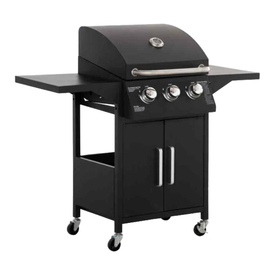
Summary of Contents for Outsunny 846-103V70
- Page 1 INb1a019_UK 846-103V70 IMPORTANT, RETAIN FOR FUTURE REFERENCE: READ CAREFULLY ASSEMBLY & INSTRUCTION MANUAL...
-
Page 3: Safety Instructions
SAFETY INSTRUCTIONS 1. Read the instruction manual carefully before use and keep it for future reference. Failure to comply with the instructions can result in death, serious injury or property damage. 2. For outdoor use ONLY! Do not use indoors. 3. -
Page 4: Part List
PART LIST Pic. Pic. M4 *8 screw +2(spare) M5*12 screw Top door pin Bottom door pin M3*nut M3*10 screw M3*10 self-tap screw... - Page 5 Assembly Note: Please do not tight the screws and nuts till all assembly steps completed. M3 * 10 screw x 2 M3*10 st x 2 M3 nut x 2 1. Assemble the LH and RH frame plates (5C) to LH & RH legs (5A, 5B, 6A &...
- Page 6 Assembly 2. Assemble the LH and RH frame to bottom shelf (7) with 4pcs M5 screws (B).
- Page 7 Assembly 3. Assemble the back shelf (9) to the frames with 4 pcs M5 screws (B).
- Page 8 Assembly 4. Assemble the front beam (8) to the front of frames with 4pcs M5 screws (B).
- Page 9 Assembly 5. Assemble the 4pcs wheels (10&11) to the end of frame legs. Note: the 2pcs wheels with break (10) are always in the same side.
- Page 10 Assembly 6. The body (1) is slided into the frame legs with 8 pcs pre-assembled M5 screws (See detailed pic.). Tight screws after body slided into position. Thermometer (23) is fixed to the lid by its own screw. Note: make sure the 8pcs screws are pre-assembled before sliding.
- Page 11 Assembly 7. LH side shelf (14) is asssembled to the body with 6 pcs M5 screws (B).
- Page 12 Assembly 8. RH side shelf (15) is asssembled to the body with 6 pcs M5 screws (B).
- Page 13 Assembly 9. Handles (13) are assembled to front doors (12) with 4pcs M4 screws (A). Totally 2 pcs doors.
- Page 14 Assembly 10. Doors are assembled to frames’ front legs with top and bottom pins (C&E).
- Page 15 Assembly 11. Warming grid (2), cooking grids (3) and heat tents (4) are fixed into the body.
- Page 16 Assembly 12. Oil cup (21) is assembled to the oil pan.
- Page 17 Assembly Tight all screws before use Assembly completed...


Need help?
Do you have a question about the 846-103V70 and is the answer not in the manual?
Questions and answers