Table of Contents
Advertisement
Advertisement
Table of Contents

Related Manuals for Emerson dixell XC650CX


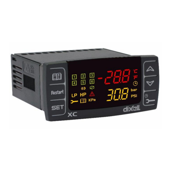
Summary of Contents for Emerson dixell XC650CX
- Page 1 XC650CX (v. 3.5)
- Page 3 INDEX BEFORE PROCEEDING XC650CX HECK THE SW REL OF THE GENERAL WARNING LEASE READ BEFORE USING THIS MANUAL AFETY RECAUTIONS GENERAL DESCRIPTION COMPONENTS RELATED TO THE XC650CX CW15KIT CW25KIT: WIRING KITS CABCJ15 CABCJ30: 2 PIN CONNECTORS PP07, PP11, PP30 PP50: 4÷20 PRESSURE TRANSDUCERS XJ485CX: TTL / RS485 SERIAL CONVERTER...
- Page 4 HOW TO DISABLED AN OUTPUT 12.1 OW TO DISABLED AN OUTPUT DURING A MAINTENANCE SESSION 12.2 UTPUT DISABLED SIGNALING 12.3 EGULATION WITH SOME OUTPUTS DISABLED RUNNING HOURS OF LOADS 13.1 OW TO DISPLAY THE RUNNING HOURS OF A LOAD 13.2 OW TO RESET THE RUNNING HOURS OF A LOAD ALARM MENU 14.1...
- Page 5 22.3 UCTION SUPERHEAT MONITORING 22.4 OT GAS INJECTION VALVE ALARM LIST 23.1 YPES OF ALARMS AND SIGNALING MANAGED 23.2 UZZER MUTING – 23.3 LARM CONDITIONS SUMMARY TABLE TECHNICAL FEATURES PARAMETERS – DEFAULT VALUES XC650CX 5/56 1592001431 XC650CX GB r3.5 21.07.2020...
-
Page 6: Before Proceeding
1. BEFORE PROCEEDING 1.1 Check the sw rel. of the XC650CX Look at the SW rel. of XC650CX printed on the label of the controller. If the SW release is 3.5, proceed, proceed with this manual otherwise contact Dixell at www.dixell.com to get the right manual. -
Page 7: General Description
3. General description The XC650CX is designed to manage both compressors and fans in a condensing system such as a pack. The compressors can be scroll or Stream, simple or multistage. It’s possible to manage up to 2 suction circuits with a common condenser. Control is by means of a neutral zone and is based on the pressure or temperature sensed in the LP suction (compressors) and HP (condenser) circuits. - Page 8 4.1 CW15KIT and CW25KIT: wiring kits The XC650CX is provided with 2 socket connectors with 14 and 12 pins. For the wiring the CW15KIT (1.5m cable length) or CWC25KIT (2.5m cable length) have to be used. 4.2 CABCJ15 or CABCJ30: 2 PIN connectors NOTE: Use the connection cable CABCJ15 (1.5m lenght) or the CABCJ30 (3.0m lenght) for the:...
-
Page 9: Wiring & Electrical Connections
5. WIRING & ELECTRICAL CONNECTIONS 5.1 General warnings Before connecting cables make sure the power supply complies with the instrument’s requirements. Separate the probe cables from the power supply cables, from the outputs and the power connections. Do not exceed the maximum current allowed on each relay 5A resistive, in case of heavier loads use a suitable external relay. - Page 10 PP07 PP11, PP30, PP50 4÷20mA pressure respect the polarity. transducers Suction (P1C = Cur) Brown (+) to terminal 6 ; white (-) to terminal 5 Condenser (P2C = Cur) 3 5 7 Brown (+) to terminal 6 ; white (-) to terminal 7 4 6 8 Suction 2 - optional (P3C = Cur) Brown (+) to terminal 6;...
-
Page 11: Analog Output Connection
5.5 SAFETY AND CONFIGURABLE DIGITAL INPUTS – FREE VOLTAGE 5.5.1 Loads safety inputs Controller has 7 configurable digital inputs, free voltage. Each digital input can be set by the related parameter iF01,.. iF07. The digital inputs are factory pre-set to operate as safety input for loads and as HP and LP. This input has to collect the status of the safety devices related to the compressor such as thermistors, pressure switches etc. -
Page 12: Mounting And Installation
Terminals Related parameter 29[+] – 30[-]. Analog output 1 AOC: Kind of signal (4-20mA/0-10V) AOF: function 8[+] – 10[-]. Analog output 2 2AOC: Kind of signal (4-20mA/0-10V) 2AOF: function 5.7 How to connect monitoring system - RS485 Serial line The XC650CX can be connected to a monitoring system thanks to the serial output. To convert the TTL to RS485 signal, the XJ485CX has to be used. -
Page 13: First Installation
7. First installation At first installation, it’s necessary the following: Select the kind of gas. Set the range of the pressure probes. In the following paragraph a short cut for the above operations. Chapters 11 Parameters programming and 0 will show in detail these operations. 7.1 How to set the kind of gas The kind of gas is set by the parameter FtyP. -
Page 14: User Interface
Press the “SET” key: the value of the parameter will start blinking. Set the lower value of the probe range. Push the SET key to confirm the value. The PA20: adjustment of read out corresponding to 20mA (4.5V) parameter will be displayed. Set the higher value of the range. -
Page 15: How To See And Modify The Set Point(S)
By holding it pressed for 3s the Maintaining menu is entered To enter the Alarm menu KEY COMBINATIONS To lock and unlock the keyboard. SET + To enter the programming mode. SET + To exit the programming mode. 8.3 Icons FUNCTION MEANING Celsius degrees... -
Page 16: The Info Menu
Push and release the SET key; The Lower display will show the “SEtC” label, while the Upper display will show its value. If second suction is configured, by pushing again the SET key the Lower display will show the “StC2” label, while the Upper display will show its value To see the fan set point, push again the SET key. -
Page 17: Parameters Programming
This information is available only if the Dynamic set point function is enabled (par. dSEP ≠ nP) • AO1 Percentage of the analog output 1 (4-20mA or 0-10V). • This information is always available • AO2: Percentage of the analog output 2 (4-20mA or 0-10V). •... -
Page 18: How To Disabled An Output
3. Press the “SET” key the value start blinking. 4. Use o or n to change its value. 5. Press “SET” to store the new value and move to the following parameter. To exit: Press SET + UP or wait 15s without pressing a key. NOTE: the new programming is stored even when the procedure is exited by waiting the time- out. -
Page 19: Alarm Menu
Push the SET key (immediately on the lower display the rSt label is displayed). Hold pushed the key for some seconds till the “rSt” label starts flashing and the lower display shows zero. To exit: push the CLOCK key or wait 30 sec NOTE: if the SET key is released within 2s, the controller reverts to display the running hours of the selected loads.. -
Page 20: How To Program An Instrument Using A Hot Key (Download)
When the controller is ON, insert the “Hot key” and push o key; the "uPL" message appears followed a by flashing “End” Push “SET” key and the End will stop flashing. Turn OFF the instrument remove the “Hot Key”, then turn it ON again. NOTE: the “Err”... - Page 21 NOTE: CONFIGURATION OF COMPRESSOR WITH UNLOADERS (STEPS): the output of compressor has to be set before the output of its unloaders (steps). ES. Compressor with 1 unloader: oA1 = cPr, oA2= StP. If compressor with different capacities are used (CtyP=dPo), all the oAi must to be configured as cPr (compressor) otherwise the configuration alarm “CStP”...
- Page 22 Plant with 4 compressors with inverter for fans: oA1 = CPr1, oA2 = CPr1, oA3 = CPr1, oA4 = CPr1, oA5 = inF* oA6 = nu AOC = tEn AOF = InF *if the inverter requires digital input to start regulation Plant with frequency...
- Page 23 oA1 = InC1, oA2 = CPr1, oA3 = CPr1, oA4 = FAn, oA5 = FAn, oA6 = nu, AOC = tEn AOF = InC1 Plant with 3 compressors suction 1 , 2 compressors suction 2, with inverter for fans: oA1 = CPr1, oA2 = CPr1, oA3 = CPr1, oA4 = CPr2,...
- Page 24 LABEL REFRIGERANT OPERATING RANGE r134 r134A -70-60°C/-94÷120°F r404A r404A -50-60°C/-58÷120°F r407A r407A -50-60°C/-58÷120°F r407C r407C -50-60°C/-58÷120°F r407F r407F -50-60°C/-58÷120°F r410 r410 -50-60°C/-58÷120°F r507 r507 -70-60°C/-94÷120°F r744 - Co2 -50-30°C/-58÷86°F -70-60°C/-94÷120°F r290 – Propane r290 -50-60°C/-58÷120°F r448 r448A -45-60°C/-69÷120°F r449 r449A -45-60°C/-69÷120°F r450 r450A...
- Page 25 17.2.2 Condenser probe configuration P2c: Condenser probe setting (probe 2): nP = not used: Cur = 4 ÷ 20 mA pressure transducer; use term. 6(+), 7 (in); 10 (gnd) if present tEn = 0.5÷4.5V ratiometric pressure transducer; use term. . 4(+), 7 (in); 10 (gnd ntc = NTC 10K probe;...
- Page 26 P3 = Probe 3 17.3 Configurable digital inputs configuration iF01 Digital input 1 configuration (10-13) nu = Not used: the digital input is disabled. oA1= Safety digital input for load 1, term. 15-17/19; (Factory setting); oA2 = Safety digital input for load 2, term. 16-17/19 oA3 = Safety digital input for load 3, term.
-
Page 27: Display And Measurement Unit
Digital input set as oA1 or Co1 activation delay (0÷255s), This delay it is considered when i1F or i2F or i3F or i4F or i5F or i6F or i7F is set as oA1 or Co1 Digital input set as oA2 or Co2 activation delay (0÷255s), This delay it is considered when i1F or i2F or i3F or i4F or i5F or i6F or i7F is set as oA2 or Co2 Digital input set as oA3 or Co3 activation delay (0÷255s), This delay it is considered when i1F or i2F or i3F or i4F or i5F or i6F or i7F is set as oA3 or Co3... - Page 28 Proportional band offset: PI band offset. It permits to move the proportional band of the PI. With rS=0 the band is between Set-Pbd/2 ÷ Set+Pbd/2; Integration time: (0 ÷ 999s) PI integration time 2Pbd Proportional band or neutral zone width for circuit 2 (0.1÷5.0bar/0.5÷30°C or 1÷150PSI/1÷50°F) The band (or zone) is symmetrical compared to the target set point, with extremes: set-Pbd/2 ÷...
-
Page 29: Alarms - Compressor Section
17.7 Fans regulation Proportional band zone width (0.1÷30.0°C; 1÷50°F; 0.1÷10.0bar, 1÷150PSI; 10÷1000KPA). NOTE: Set the dEU par. and the target set point for fans before setting this parameter. The band is symmetrical compared to the target set point, with extremes: SETF+Pb/2 ÷ SETF -Pb/2. - Page 30 SEr: Service request: (1÷999 hours, res. 10h; 0 = alarm excluded ) number of running hours after that the “A14” maintenance call is generated. PEn: Low pressure-switch intervention numbers: (0÷15). If the low pressure-switch is enabled PEn times in the PEI interval, the controller is locked. Only the manually unlocking is possible.
- Page 31 The low superheat pre-alarm warning is sent when the superheat (SH) is lower than ASH2 (low superheat alarm threshold) + ASH0, possibly after the ASH1 delay. ASH1 Delay for signalling low superheat pre-alarm (0÷255sec) If the superheat is below the ASH2+ASH0 threshold for ASH1 time the low superheat pre-alarm warning is sent.
- Page 32 Analog output 1 function nu = analog output disabled; Inc1= To drive inverter for suction frequency compressor, suction of circuit 1; Inc2 = To drive inverter for suction frequency compressor, suction of circuit 2 inF= to drive ECI fan or inverter for fan InCP Inverter compressor always activated at first: no: other compressors if available are allowed to start when the inverter compressor is...
-
Page 33: Even Capacity Compressors (Ctyp = Spo)
Software release for internal use. Sub-Release firmware for internal use Parameter table code: readable only. Access to Pr2 parameter level 18. Even Capacity Compressors (CtyP = Spo) 18.1 Compressors With Same Capacity – Dead band control This regulation is applied both to the circuit 1 and the circuit 2. The neutral zone (Pbd) is symmetrical compared to the target set point, with extremes: set+Pbd/2 ... -
Page 34: Uneven Capacity Compressors (Ctyp = Dpo)
19. UNEVEN CAPACITY COMPRESSORS (CtyP = dPO) With CtyP = dPO the regulation is performed for uneven capacity compressors In this case the capacity supplied by the system is a combination of the capacity of different compressors. The capacity of each compressor ha sto be set in the parameters PC1…PC6. The regulation algorithm supply a combination of the available capacities, starting from the lower ones and increasing step by step according to the requests coming from the system. -
Page 35: Relay Activation
20.1 Regulation with screw compressors like Bitzer/ Hanbell/ Refcomp etc Screw compressors like Bitzer use up to 3 valves for the power regulation. 20.1.1 Relay activation ES. Compressor with 4 steps: oA1 = CPr1; oA2 = StP; oA3 = StP; oA4 = StP; CtyP = Scr a. - Page 36 ALL LOADS ON Set+Pb/2 Set+Pb/4 SETF Set-Pb/4 Set-Pb/2 ALL LOADS OFF 21.1 Condenser with Inverter or Eci Fans–Analog Output Setting This configuration is used when all fans of the condensing group are ECI fans or driven by one inverter or a chopped phase driver. The capacity used by the inverter is proportional to the delivery pressure value inside the regulation band (SETF-Pb/2÷...
- Page 37 21.1.2 How to set it Parameters involved: oA(i) = inF; AoC = tEn, AoF = InF, Aot = 0, AOM = 30, MPM = 100 Volt SETF-Pb/2 SETF- Pb 100-2AOM OAi = inF SETF-Pb/2 SETF+Pb/2 If required, set a relay to drive the invert (is used to signal to the inverter to start and stop the oA(i) = inF inverter for fans regulation), by setting: Set the kind of signal of the analog output current (4-20ma) or voltage (0-10V) by the...
- Page 38 Parameter Description Action AOt = 5 Time of analog output at max With AOt = 5 the controller supplies 10V output after the start for 5s at fan start, then starts standard regulation MPM = 100 Maximum % variation per The analog output takes 1 min to move from minute the min to the maximum...
-
Page 39: Additional Functions
22. Additional functions 22.1 Compressor running proof function The digital inputs are normally used to signal a compressor or fan failure It’s also possible to set the digital inputs for running proof signalling. That means when compressor relay is activated, after a configurable delay the digital input related to the compressor should goes on too (usually a contact from compressor contactor) and the controller has the “confirmation”... - Page 40 22.2 Flood protection function To ensure the maximum safety of the plant, a relay is activated when the compressors can’t be switched on since they are blocked due to safety times or for other issues or stopped for maintenance. This output can be used to block the liquid injection to the cabinets to avoid to flood the suction collectors.
- Page 41 22.3 Suction superheat monitoring Controller can monitor the suction superheat, and signal situations of low superheat, with a pre - alarm and alarm thresholds. According to the settings, compressors can be stopped in case of low superheat alarm, to preserve compressor integrity. 22.3.1 Suction Superheat detecting To detect the suction superheat an auxiliary probe among P3 (term.
-
Page 42: Special Conditions
22.4 Hot gas injection valve Controller can manage a hot gas injection valve to increase suction superheat. See above figure. 22.4.1 Parameters A relay must be set as hot gas valve: oA2 or oA3 or oA4 or oA5 or oA6= HGi, and an auxiliary probe among P3 (term. - Page 43 Mess. Errata Corrige • Too Many dGS More than one oAi has Check the oAi parameters and set output been set as dGs (digital them different from dGS. scroll) • Too Many dGSt One oAi has been set as Check the oAi parameters and set output dGst (triac for digital them different from dGSt.
- Page 44 Mess. Errata Corrige The kind of outputs are • CPr Circuit Check parameters oA(i) , CtyP and not compatible with the 2 conFiG Error set CtyP different from Scr. suction circuits AO1 And AO2 AoF and 2AoF have the • SAME Set AoF and 2AoF properly.
- Page 45 Parameters iP07: Low pressure switch 2 polarity: It establishes if the input is activated by giving (iP07=cL) or by removing (iP07=oP) main voltage to the terminals. Actions Low pressure switch 2: every time the inputs are activated all the compressors of circuit 2 are switched off.
-
Page 46: Alarm Conditions - Summary Table
23.2 Buzzer muting Press any buttons to silence the buzzer during an alarm condition. Hold pressed for more than 3 seconds switch off the alarm relay during an alarm condition 23.3 Alarm conditions – summary table Code Description Cause Action Reset E01L Pressure/temperat... - Page 47 Code Description Cause Action Reset P3 probe Probe 3 failure or − Automatically as soon as the probe restarts With P3 used failure alarm out of range working. for circuit 2, the compressors are activated according to the 2SPr. − The functions related to the third probe are...
- Page 48 Code Description Cause Action Reset Inverter fan The configurable The analog out set Automatically as soon as the input is disabled alarm dig. Input set as as INF is switched inF is activated FC01 Running The digital input set The compressor 1..4 Automatic –...
-
Page 49: Technical Features
24. Technical features XC650CX Housing: Self-extinguishing PC/PC+ABS. Case: Front panel 32x74 mm, depth 60mm. Mounting device: panel mounting in a 29x71 mm panel cut-out Degree of protection: Indoor use, Type 1 enclosure (NEMA - UL 50e); Frontal panel: IP65; Rear housing: IP20. ... -
Page 50: Parameters - Default Values
25. Parameters – Default values Label Value Menu Description Range Set point for compressors LSE÷HSE -10.0 StC1 Set point for compressors circit 2 2LSE÷2HSE StC2 -30.0 Set point for fans LSF÷HSF SEtF 35.0 Load 1 configuration nu - CPr1 - CPr2 - StP - dGS - 6dG - dGSt - InC1 - InC2 - FAn - InF - LIn –... - Page 51 Label Value Menu Description Range 4mA or 0.5V readout for P3 probe (-1.0 ÷ FA20)BAR; (-15 ÷ FA20)PSI; (- 3P04 -0.5 100 ÷ FA20)KPA 20mA or 4.5V readout for P3 probe (3P04 ÷ 61.0)BAR; (3P04 ÷ 885)PSI; 3P20 11.0 (3P04 ÷ 6100)KPA P3 probe offset -12.0÷12.0(°C);...
- Page 52 Label Value Menu Description Range Measurement unit for temperature °C - °F °C Measurement unit for pressure BAr - PSI - PA Resolution for display and parameters in - dE Upper display: pressure or temperature tMP - PrS dEU1 selection Lower display default visualization nu - P1 - P2 - P3 - P4 - StC1 - StC2 - dSP2...
- Page 53 Label Value Menu Description Range Proportional band for fan regulation 0.1÷30.0(°C) 1÷50 (°F) 0.1÷10.0(BAR) 1÷150(PSI) 10÷1000(KPA) Energy saving differential for fan regulation -50.0÷50.0(°C) -90÷90(°F) -20.0÷20.0(BAR) -300÷300(PSI) -2000÷2000(KPA) Band offset for fan regulation in ES -50.0÷50.0(°C) -90÷90(°F) -20.0÷20.0(BAR) -300÷300(PSI) PbES -2000÷2000(KPA) Time delay between the insertion of two 0 ÷...
- Page 54 Label Value Menu Description Range Fan pressure switch maximum activations 0 ÷15 Fan pressure switch activations time 0 ÷ 255 (min) Fan ON with faulty probe 0 ÷ 6 Differential for low superheat pre-alarm 0.1 to 30.0°C/ 1 to 60°F ASH0 Delay for signalling low superheat pre-alarm 0÷255 sec...
- Page 55 Label Value Menu Description Range Serial address 1 ÷ 247 Release firmware Readable only Sub-Release firmware Readable only Parameter table code Readable only Pr2 access Readable only XC650CX 55/56 1592001431 XC650CX GB r3.5 21.07.2020...
- Page 56 XC650CX 56/56 1592001431 XC650CX GB r3.5 21.07.2020...
Need help?
Do you have a question about the dixell XC650CX and is the answer not in the manual?
Questions and answers