Table of Contents
Advertisement
Advertisement
Table of Contents

Subscribe to Our Youtube Channel
Related Manuals for Emerson Dixell XC645CX


Summary of Contents for Emerson Dixell XC645CX
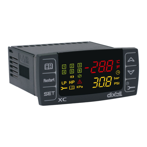
- Page 1 XC645CX (v. 3.4)
- Page 2 INDEX BEFORE PROCEEDING XC645CX HECK THE SW REL OF THE GENERAL WARNING LEASE READ BEFORE USING THIS MANUAL AFETY RECAUTIONS GENERAL DESCRIPTION COMPONENTS RELATED TO THE XC645CX CWC15KIT CWC30KIT: WIRING KITS CABCJ15 CABCJ30: 2 PIN CONNECTORS PP07, PP11, PP30 PP50: 4÷20 PRESSURE TRANSDUCERS NP4-67: PIPE MOUNTING TEMPERATURE PROBE...
- Page 3 “P 2” 11.2 OW TO ENTER IN PARAMETERS LIST 11.3 OW TO CHANGE PARAMETER VALUES HOW TO DISABLED AN OUTPUT 12.1 OW TO DISABLED AN OUTPUT DURING A MAINTENANCE SESSION 12.2 UTPUT DISABLED SIGNALING 12.3 EGULATION WITH SOME OUTPUTS DISABLED RUNNING HOURS OF LOADS 13.1 OW TO DISPLAY THE RUNNING HOURS OF A LOAD...
- Page 4 ALARM LIST 20.1 YPES OF ALARMS AND SIGNALING MANAGED 20.2 UZZER MUTING – 20.3 LARM CONDITIONS SUMMARY TABLE TECHNICAL FEATURES PARAMETERS – DEFAULT VALUES 1592001440 XC645CX GB r3.4 31.10.2017.docx XC645CX 4/54...
-
Page 5: Before Proceeding
1. BEFORE PROCEEDING 1.1 Check the sw rel. of the XC645CX Look at the SW rel. of XC64D printed on the label of the controller. If the SW release is 3.4, proceed with this manual otherwise contact Dixell to get the right manual. - Page 6 Control is by means of a neutral zone or proportional band and is based on the pressure or temperature sensed in the LP suction (compressors) and HP (condenser) circuits. A special algorithm balances the run hours of the compressors to distribute the work load uniformly. The controllers can convert both suction and discharge pressures and displays them as temperatures.
- Page 7 4.2 CABCJ15 or CABCJ30: 2 PIN connectors NOTE: Use the connection cable CABCJ15 (1.5m lenght) or the CABCJ30 (3.0m lenght) for the: HP digital input (25-26), i2F configurable digital input (27- 28), 0-10Vdc 4-20mA analogue output (23-24) oA6, 12Vdc/40mA digital output (21- 22) : 4.3 PP07, PP11, PP30 PP50: 4÷20mA pressure transducers NAME...
-
Page 8: Wiring & Electrical Connections
5. WIRING & ELECTRICAL CONNECTIONS 5.1 General warnings Before connecting cables make sure the power supply complies with the instrument’s requirements. Separate the probe cables from the power supply cables, from the outputs and the power connections. Do not exceed the maximum current allowed on each relay 3A resistive, see also Technical Features, in case of heavier loads use a suitable external relay. - Page 9 5.3 Probes connection 5.3.1 General warnings If using terminal ends be sure there are no bear parts which could cause short circuiting or introduce noise disturbance at high frequencies. To minimize the induced disturbances use shielded cables with the shield connected to earth. Pressure probe (4 - 20 mA): respect the polarity.
-
Page 10: Load Connections
5.4 LOAD CONNECTIONS !!!WARNING: Digital Scroll valve coil MUST operate at main voltage (230Vac or 115Vac)!!!! NOTE: Main voltage side (6PINs connector): the PIN 17 is the common line for all the relay outputs and for the TRIAC. 5.5 SAFETY AND CONFIGURABLE DIGITAL INPUTS – FREE VOLTAGE 5.5.1 Loads safety inputs !!!WARNING: free voltage inputs!!!! -
Page 11: Analog Output Connection
PRESSURE SWITCH INPUT TERMINALS SETTING 10-9 iF05 = LP1 25-26 iF06 = HP * The digital input 6 (25-26) requires the adapter CABCJ15 or CABCJ30 to be used. See par. Error! Reference source not found. Error! Reference source not found. 5.5.3 Additional function of the digital input 7 (27-28) The digital input 7 can operate also as probe. -
Page 12: Mounting And Installation
6. Mounting & installation The instruments are suitable only for internal use. Instruments shall be mounted on panel, in a 29x71 mm hole, and fixed using the special brackets supplied. The ambient operating temperature range is between -10÷60°C. Avoid locations subject to heavy vibration, corrosive gases or excessive dirt. The same applies to the probes. -
Page 13: First Installation
7. First installation At first installation, it’s necessary the following: Select the kind of gas. Set the range of the pressure probes. In the following paragraph a short cut for the above operations. Chapters 11 Parameters programming and 17 will show in detail these operations. 7.1 How to set the kind of gas The controller has memorized the relation between temperature and pressure for some gases. -
Page 14: User Interface
Push the SET key to confirm the value. Next parameter will be displayed. Do the same things for the Probe 2, FA04, FA20 parameters. 8. User interface 8.1 Displaying UPPER DISPLAY LOWER DISPLAY ICONS Suction temperature or Discharge temperature or pressure - Working loads pressure Measurement unit... -
Page 15: How To See And Modify The Set Point(S)
KEY COMBINATIONS To lock and unlock the keyboard. SET + To enter the programming mode. SET + To exit the programming mode. 8.3 Icons FUNCTION MEANING Celsius degrees Fahrenheit degrees bar displaying PSI displaying KPA displaying Digital scroll compressor (DGS) on Flashing DGS is waiting to start (1HZ) or digital input alarm for DGS (2Hz). -
Page 16: The Info Menu
9.2 How to modify the set point of compressors and/or fans ******WARNING: before setting the target set points for the first time, check and, if necessary, modify the type of freon (par. FtyP) and the default unit of measurement (par. dEU) for compressors and fans ********** PRE-ACTION Set the kind of freon by means of the FtyP parameter (see 7.1 How to set the kind of... -
Page 17: Parameters Programming
• This information is always available • SSC1: Supervising Set for circuit 1, if supervising system is sending the set point to the controller • SSC2: Supervising Set for circuit 2, if supervising system is sending the set point to the controller •... -
Page 18: How To Disabled An Output
NOTE: the new programming is stored even when the procedure is exited by waiting the time- out. 12. How to disabled an output To disabled an output during a maintenance session means to exclude the output from the regulation. 12.1 How to disabled an output during a maintenance session. Push the MAINTENANCE/CLOCK ( ) key for 3s. -
Page 19: Alarm Menu
Select the load by pressing the UP key. Push the SET key (immediately on the lower display the rSt label is displayed). Hold pushed the key for some seconds till the “rSt” label starts flashing and the lower display shows zero. To exit: push the CLOCK key or wait 30 sec NOTE: if the SET key is released within 2s, the controller reverts to display the running hours of the selected loads.. -
Page 20: List Of Parameters
16. Use of the programming “HOT KEY “ 16.1 How to program a hot key from the instrument (UPLOAD) Program one controller with the front keypad. When the controller is ON, insert the “Hot key” and push o key; the "uPL" message appears followed a by flashing “End”... - Page 21 NOTE: also the “dGs” “CPr2” “inC1”, “inC2”and “dGSt” values are present. These values must not be used.. According to the oA2, oA3, oA4, oA6 configuration, 2 kinds of plant can be defined: Rack with compressors only: all the oAi different from FAn and inF Rack with compressors and fans: both FAn and CPr are used for oAi.
- Page 22 dGty Kind of digital compressor SCrL = Digital Scroll: the range of capacity modulation starts from 10% to 100% StrM = Digital Stream: the range of capacity modulation starts from 0% to 100% Valve outputs (unloader) polarity: polarity of the outputs for capacity valves. It determines the status of the relays associated with the capacity valves (only for homogeneous and stepped-capacity compressors) oP=valve activated with open contacts of the relay;...
- Page 23 tEn = 0.5÷4.5V ratiometric pressure transducer; use term. 4(+), 5 (in); 10 (gnd) ntc = NTC 10K probe; use term. 4- 5 PA04: Adjustment of read out for the Probe 1 (used only if Pbc=Cur or tEn). Corresponding to 4mA or 0.5V input signal, given by the suction probe (-1.0 ÷ PA20bar; -15÷PA20PSI; -100 ÷...
-
Page 24: Others Inputs Configuration
P1 = Probe 1 P2 = Probe 2 P3 = Probe 3 17.3 Others inputs configuration iF01 Digital input 1 configuration (10-13) nu = Not used: the digital input is disabled. oA1= Safety digital input for load 1, term. 15-17; (Factory setting); oA2 = Safety digital input for load 2, term. -
Page 25: Display And Measurement Unit
iP07 Digital input 7 polarity (27-28): oP: the digital input is activated by opening the contact; CL: the digital input is activated by closing the contact. Digital input set as oA1 or Co1 activation delay (0÷255s), This delay it is considered when i1F or i2F or i3F or i4F or i5F or i6F or i7F is set as oA1 or Co1 Digital input set as oA2 or Co2 activation delay (0÷255s), This delay it is considered when i1F or i2F or i3F or i4F or i5F or i6F or i7F is set as oA2 or Co2... -
Page 26: Compressor Regulation
17.5 Compressor regulation Pbd: Proportional band or neutral zone width (0.1÷5.0bar/0.5÷30°C or 1÷150PSI/1÷50°F) The band (or zone) is symmetrical compared to the target set point, with extremes: set- Pbd/2 ÷ set+Pbd/2. It is used as proportional band for PI algorithm. The measurement unit depends on the dEU, CF, PMU par. -
Page 27: Alarms - Compressor Section
LSE: Minimum set point: The measurement unit depends on dEU parameter. It sets the minimum value that can be used for the set point, to prevent the end user from setting incorrect values. HSE: Maximum set point: The measurement unit depends on dEU parameter. It sets the maximum acceptable value for set point. -
Page 28: Suction Superheat
unlocking is possible. See also the alarms table at paragraph 18.4. Every time the pressure-switch is enabled all the compressor are turned off. PEI: Pressure-switch interventions time (0÷15 min) Interval, linked to the Pen parameter, for counting interventions of the low pressure-switch.. SPr: number of steps engaged with faulty probe. -
Page 29: Analog Outputs (Optional)
The low superheat pre-alarm warning is sent when the superheat (SH) is lower than ASH2 (low superheat alarm threshold) + ASH0, possibly after the ASH1 delay. ASH1 Delay for signalling low superheat pre-alarm (0÷255sec) If the superheat is below the ASH2+ASH0 threshold for ASH1 time the low superheat pre-alarm warning is sent. - Page 30 cUr = 4-20mA output Analog output function nu = analog output disabled; Inc1= To drive inverter for suction frequency compressor ; Inc2 = not set it inF= to drive ECI fan or inverter for fan FrE = “Free”, proportional to the probe P3 and P4. Probe for analog output: It is used only if AOP=FrE nP = no probe;...
- Page 31 no = the buzzer is not used in case of alarm yES = buzzer is used in case of alarm Serial address (1 –247) It is used in monitoring system. Adr: Software release for internal use. Parameter table code: readable only. Access to Pr2 parameter level 1592001440 XC645CX GB r3.4 31.10.2017.docx XC645CX...
-
Page 32: Type Of Regulation
18. Type of regulation 18.1 DIGITAL COMPRESSOR REGULATION 18.1.1 Digital scroll: main parameters set up EG: Plant with 2 compressors (one of them digital) e 2 fans default configuration with PP11, PP30 pressure transducers: oA1 = dGS oA2 = CPr1, oA3 = FAn, oA4 = FAn, dGty = SCrL... - Page 33 NOTE: At start up the valve is energized for SUt seconds. Within the adjustment range (SET–Pbd/2 ÷ SET+Pbd/2) the digital scroll compressor is activated in PWM mode in accordance with the value of the control variable. (NOTE: When the TRIAC is on the compressor is discharged; when the TRIAC is off the compressor is operative).
- Page 34 18.1.4 Digital Stream: Main parameters set up EG: Plant with 2 compressors Stream 6D and 2 fans default configuration with PP11, PP30 pressure transducers: oA1 = dGS oA2 = 6dG oA3 = FAn, oA4 = FAn, dGty = StrM The pressure is adjusted by a PI regulation, following the same logic of the digital scroll see previous paragraphs: 18.1.2Error! Reference source not found.
- Page 35 The capacity of the DGS compressor is limited by the PM and PMA parameters, where PM: in percentage, it sets the minimum capacity of the DGS activation during a period tdS. For instance with tdS = 20s and PM = 20, the minimum activation of the DGS is 4s. NOTE For digital scroll (dGty = SCrL) the minimum allowed value of PM is 10 For digital stream (dGty = StrM) the minimum allowed value of PM is 0...
- Page 36 18.2 Proportional Band regulation - only for fans The fan regulation band Pb is divided by the number of fans: The numbers of fans switched ON is proportional to the value of the input signal: when this distances itself from the target set point and enters the various bands, the compressors are switched ON, to be then turned OFF when the signal brings near the set point.
- Page 37 18.3 Condenser with Inverter or Ec Fans–Analog Output Setting This configuration is used when all fans of the condensing group are ECI fans or driven by one inverter or a chopped phase driver. The capacity used by the inverter is proportional to the delivery pressure value inside the regulation band (SETF-Pb/2÷...
- Page 38 18.4 Analog output “free” This setting is used to link the analog output 1 to a temperature probe. The analog output will take values proportional to the temperatures detected by the probe P3 or P4, according to the setting. 18.4.1 Analog output “free” configurations and Parameters Parameter Description Action...
-
Page 39: Additional Functions
Set the end scale temperature by UAO parameter, at which correspond the maximum value of analog output Set the max % variation per min (MPM) At last set also the percentage of analog output in case of probe failure: (0 ÷ 100%)SAO 19. - Page 40 When the compressor 1 (or 2) starts, if by 2sec the digital input 3 (or 4) is not activated (running proof function) the FC01 alarm is signalled and the compressor is stopped. Alarm recover as soon as the safety timers of the compressor (onon, ofon) are over and compressor come back available for regulation.
- Page 41 19.3 Suction superheat monitoring Controller can monitor the suction superheat, and signal situations of low superheat, with a pre- alarm and alarm thresholds. According to the settings, compressors can be stopped in case of low superheat alarm, to preserve compressor integrity. 19.3.1 Suction Superheat detecting To detect the suction superheat an auxiliary probe among P3 (term.
-
Page 42: Special Conditions
19.4 Hot gas injection valve Controller can manage a hot gas injection valve to increase suction superheat. See above figure. 19.4.1 Parameters A relay must be set as hot gas valve: oA2 or oA3 or oA4 or oA5 or oA6= HGi, and an auxiliary probe among P3 (term. - Page 43 Mess. Errata Corrige • Too Many dGS More than one oAi has Check the oAi parameters and set output been set as dGs (digital them different from dGS. scroll) • Too Many dGSt One oAi has been set as Check the oAi parameters and set output dGst (triac for digital them different from dGSt.
- Page 44 Mess. Errata Corrige The kind of outputs are • CPr Circuit Check parameters oA(i) , CtyP and not compatible with the 2 conFiG Error set CtyP different from Scr. suction circuits AO1 And AO2 AoF and 2AoF have the • SAME Set AoF and 2AoF properly.
- Page 45 The terminals (from 10, 11, 12, 13, 14+ ID5) really used depends on the number of loads. The protections regarding the compressors and fans are connected to these inputs. If one of these protections is enabling (E.I. for lack of oil or overheating, etc,) the corresponding load is turn off. Parameters ALIP: It establishes if the input is activated by closing (ALIP=cL) or by opening (ALIP=oP) the terminals.
-
Page 46: Alarm Conditions - Summary Table
20.3 Alarm conditions – summary table Code Description Cause Action Reset EI1L Pressure/temperature All compressors are Automatically when the pressure/temperature electronic less than ELP value turned off. Fans increases more than ELP value pressure- unchanged. switch alarm E0L1 Low Low pressure switch All compressors are Automatically (if the number of activation are pressure-... - Page 47 Code Description Cause Action Reset Load safeties Safeties Recovery depends on ALMr parameter: alarm compressor/fan input With ALMr = no The instrument restart the corresponding activation. standard operating mode when the input is load is turned NOTE: with step disabled.
- Page 48 Code Description Cause Action Reset PrSH Low Automatic: The superheat is Only warning superheat when superheat: less than: SH< Pre-allarm SH>ASH0+ASH2+1°C(2°F) ASH2 + ASH0 for ASH1 time ALSH Low Automatic: The superheat is Regulation superheat when superheat: less than: SH< depends allarm SH>...
-
Page 49: Technical Features
21. Technical features Housing: Self extinguishing ABS. Front panel 32x74 mm, depth 70mm (“CX” format); Case: Mounting: “CX” format panel mounting in a 29x71 mm panel cut-out Protection: IP20. Frontal protection: IP65. Connections: Removable terminal block 6 and 14 ways; ... -
Page 50: Parameters - Default Values
22. Parameters – Default values Value Menù Description Range Label Set point for compressors LSE÷HSE -10.0 StC1 Set point for fans LSF÷HSF SEtF 30.0 Load 1 configuration nu - CPr1 - CPr2 - StP - dGS - 6dG - dGSt - InC1 - InC2 - FAn - InF - LIn –... - Page 51 Value Menù Description Range Label Configurable digital input 1 function nu - OA1- OA2 - OA3 - OA4 - OA5 - OA6 - (terminals 10-13) InF - LP1 - LP2 - HP - ES - OFF - LL - SIL – iF01 EAL –...
- Page 52 Value Menù Description Range Label Cycle time for digital compressor 10÷40s Minimum capacity for digital compressor 10÷PMA(dGty=ScrL) 0÷PMA(dGty=StrM) Maximum capacity for digital compressor PM÷100 Time with digital compr. at PMA value before 0÷255s starting a load Time with digital compr. at PM before turning 0÷255s off a load Minimum capacity threshold to start the...
- Page 53 Value Menù Description Range Label Pressure/temperature alarm delay 0 ÷ 255 (min.) (compressors) Electronic pressure switch threshold -50.0÷STC1(°C) -58÷STC1(°F) -45.0 PA04÷STC1(BAR , PSI , KPA) Working hour alarm set (tenth of ours) 1 ÷ 999 (0= disabled) (10 hour) Pressure switch maximum activations 0 ÷...
- Page 54 Value Menù Description Range Label Temperature value associated to the maximum value of analog output, 10V or 20mA -50.0÷150.0(°C) -58÷302(°F) Minimum value of analogue output 0 ÷ 100 (%) Time with analog output at max when after 0÷15s exceeding AOM Maximum % variation per minute nu, 1 ÷...
Need help?
Do you have a question about the Dixell XC645CX and is the answer not in the manual?
Questions and answers