Table of Contents
Advertisement
& K D S W H U
System Board
1.1
Features
The V58LA is an all-in-one Pentium-based system board that utilizes
the PCI local bus architecture. It is capable of offering multimedia and
network functions by simply integrating a VGA controller with 3D
support, a Sound Blaster-compatible audio chip, and a Fast Ethernet
controller.
The system memory is expandable to 256 MB via two onboard 168-pin
DIMM (double in-line memory module) sockets. To further enhance
system performance, the board also comes with 256-/512-KB
pipelined-burst second-level cache and 1/2/4-MB video memory.
Standard onboard I/O interfaces comprise of two UART 16C550 serial
ports, a parallel port with Enhanced Parallel Port (EPP)/Extended
Capabilities Port (ECP) feature, PS/2 keyboard and mouse ports, and
VGA port. Two Universal Serial Bus (USB) interfaces are added to the
design to enable the system to support more peripherals. For full
multimedia support, video, audio and network interfaces are also
provided.
Other special features supported are Hardware Monitoring and
Wake-on Ring-in functions. For details, read the following sections.
The system is fully compatible with Windows 95, Windows NT,
NetWare, MS-DOS V6.X, OS/2, and UNIX operating systems.
System Board
1-1
Advertisement
Table of Contents

Related Manuals for Acer AcerPower 3000


Summary of Contents for Acer AcerPower 3000
-
Page 1: System Board
& K D S W H U System Board Features The V58LA is an all-in-one Pentium-based system board that utilizes the PCI local bus architecture. It is capable of offering multimedia and network functions by simply integrating a VGA controller with 3D support, a Sound Blaster-compatible audio chip, and a Fast Ethernet controller. -
Page 2: Major Components
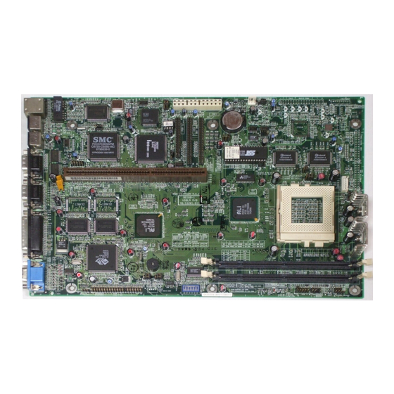
Major Components The system board has the following major components: A ZIF (zero insertion force) socket that supports 3.3V Intel Pentium P54C/P55C processor running at 90/60, 100/66, 120/60, 133/66, 150/60, 166/66, 200/66, or 233/66 MHz. Also supports Cyrix M1/M2 or AMD K5/K6 processor Two 168-pin DIMM sockets that accept SDRAMs with 8, 16, 32, 64, and 128-MB capacities (256-MB maximum system memory) 256-KB or 512-KB pipelined-burst second-level cache... - Page 3 Layout Figure 1-1 shows the board layout and the locations of the important components. Riser card slot Ultra I/O controller LAN controller Power connector Battery Standby connector BIOS chip Audio controller AIO board connector Fax/modem connector CD-in and Line-in connectors Pipelined-burst cache Voltage regulators with heatsink 29 DIMM sockets...
-
Page 4: Jumper And Connector Locations
The heatsink becomes very hot when the system is on. NEVER touch the heatsink with any metal or with your hands. Jumpers and Connectors 1.4.1 Jumper and Connector Locations Figure 1-2 shows the jumper and connector locations. Figure 1-2 Jumper and Connector Locations The shaded pin indicates pin 1. -
Page 5: Jumper Settings
CN23 1-3, 2-4 3-5, 4-6 CN36 9-10 Switch 1 System Board Function BIOS Logo Acer LED Function for IDE and FDD for IDE only Suspend/Reset Switch Function Suspend Reset L2 Cache Mode Intel or Cyrix M1/M2 “1+4” mode Cyrix M1/M2 linear-burst mode Power Supply Type With standby power current >... - Page 6 Table 1-1 Jumper Settings (continued) Jumper Setting Switch 2 Switch 3 Switch 6 Table 1-2 Host Bus Frequency Select Jumper 60 MHz CY2273 JP14 1-3, 2-4 JP15 1-3, 2-4 Table 1-3 CPU/Host Bus Frequency Ratio Select JP11 switch 4 switch 5 Function Onboard Sound Disabled...
- Page 7 Table 1-4 CPU Type and Frequency Select Freq. (MHz) JP11 JP14 JP15 Intel P54C 1-3, 2-4 1-3, 2-4 P100 1-3, 2-4 3-5, 4-6 P120 1-3, 2-4 1-3, 2-4 P133 1-3, 2-4 3-5, 4-6 P150 1-3, 2-4 1-3, 2-4 P166 1-3, 2-4 3-5, 4-6 P200 1-3, 2-4...
-
Page 8: Onboard Connectors
Table 1-4 CPU Type and Frequency Select (continued) Freq. (MHz) JP11 JP14 JP15 AMD K5 PR90 1-3, 2-4 1-3, 2-4 PR100 1-3, 2-4 3-5, 4-6 PR120 1-3, 2-4 1-3, 2-4 PR133 1-3, 2-4 3-5, 4-6 PR166 1-3, 2-4 3-5, 4-6 AMD K6 PR166 1-3, 2-4... - Page 9 Table 1-5 Onboard Connectors (continued) Connector Monitor port USB board connector CN10 Standby power connector CN11 Power connector CN12 Floppy disk drive connector CN13 IDE 2 connector CN14 IDE 1 connector CN15 AIO board connector CN18 CD-in connector CN19 Line-in connector CN22 Two-pin fan connector CN26...
-
Page 10: Esd Precautions
ESD Precautions Electrostatic discharge (ESD) can damage your processor, disk drives, expansion boards, and other components. following precautions before you install a system component. Do not remove a component from its protective packaging until you are ready to install it. Wear a wrist grounding strap and attach it to a metal part of the system unit before handling components. -
Page 11: Installing Memory
Installing Memory The system memory is upgradable to a maximum of 256 MB via two 168-pin DIMM sockets onboard. These DIMM sockets accept 8, 16, 32, 64, and 128-MB, 3.3V SDRAMs. See Figure 1-1 for the location of the DIMM sockets. Section 1.7.1 tells how to install DIMMs. Table 1-6 lists the possible memory configurations. -
Page 12: Installing A Dimm
1.7.1 Installing a DIMM Follow these steps to install a DIMM: Align pin 1 of the DIMM with pin 1 of the socket. Pin 1 is labeled 1 on both of the DIMM and the socket. Gently push the DIMM until the holding clips lock the DIMM into a vertical position. -
Page 13: Removing A Dimm
1.7.2 Removing a DIMM To remove a DIMM: Press the holding clips on both sides of the socket outward to release the DIMM. Gently pull the DIMM out of the socket. Figure 1-4 Removing a DIMM 1.7.3 Reconfiguring the System The system automatically detects the amount of memory installed. -
Page 14: Second-Level Cache
Second-level Cache The board may come with either 256-KB or 512-KB pipelined-burst second-level cache. Refer to the following table for the possible cache configurations. Table 1-7 Second-level Cache Configurations Cache Data RAM Location Size (12 ns) 256 KB 32K x 32 x 2 pcs. U24, U25 512 KB 64K x 32 x 2 pcs. -
Page 15: Installing The Upgrade Cpu
1.9.2 Installing the Upgrade CPU Observe the ESD precautions when installing components. See section 1.5. Before you proceed, make sure that there is no CPU installed in the CPU socket. Follow these steps to install the upgrade CPU: Pull up the socket lever. Insert the CPU, making sure that pin 1 (indicated by a notched corner) of the CPU connects to hole 1 of the socket. -
Page 16: Ide Hard Disk Support
Figure 1-6 Attaching the Heatsink and Fan to the CPU Plug the fan cable to the fan connector on the system board. 1.10 IDE Hard Disk Support The system board supports four IDE hard disks, or any other IDE devices, through the two onboard PCI IDE interfaces. See Figure 1-2 for the location of the IDE interfaces. -
Page 17: Video Memory
1.11 Video Memory 1.11.1 Video Memory Configurations The system board may come with 1, 2, or 4-MB SGRAM video memory. Larger video memory allows you to display higher resolutions and more colors. The following table lists the possible video memory configurations. Table 1-9 Video Memory Configurations Memory Size... - Page 18 Table 1-10 Supported Video Resolutions (continued) Resolution V-Freg. 800 x 600 8/16 800 x 600 8/16 800 x 600 8/16 800 x 600 800 x 600 1024 x 768 8/16 43 int. 1024 x 768 8/16 1024 x 768 8/16 1024 x 768 8/16 1024 x 768...
-
Page 19: Expansion Cards
1.12 Expansion Cards 1.12.1 Installing a Riser Card A riser card is a card that contains the PCI and ISA slots. enables you to add functions to your system further enhance its performance. To install a riser card: Locate the riser card slot on the system board. Gently insert a riser card into the slot. -
Page 20: Installing A Pci Card
1.12.2 Installing a PCI Card To install a PCI card: Locate the PCI slot(s) on the slot board. Remove the bracket on the housing opposite to the empty PCI slot. Insert a PCI card into the slot. Make sure that the card is properly seated. -
Page 21: Installing Isa Cards
1.12.3 Installing ISA Cards Both PnP and non-PnP ISA cards require specific IRQs. installing ISA cards, make sure that the IRQs required by these cards are not previously assigned to PCI devices to avoid resource conflicts. Follow these steps when installing ISA cards: Remove all PnP cards installed in the system, if any. -
Page 22: Post-Installation Instructions
1.13 Post-installation Instructions Observe the following after installing a system component: See to it that the components are installed according to the step- by-step instructions in their respective sections. Make sure you have set all the required jumpers. See section 1.4.2. -
Page 23: Wake-On Lan Function
1.15 Hardware Monitor Function The Hardware Monitor function of the system board allows you to check the system resources, either locally or in a computer network, via software such as ADM (Advanced Desktop Management) or Intel LDCM (LAN Desk Client Manager) ). desktop management programs that offer SMART (System Monitoring Analysis and Reporting Technology) monitor function for checking local or network connected systems. -
Page 24: Software Error Messages
1.18 Error Messages In the event that you receive an error message, do not continue using the computer. Note the message and take corrective action immediately. This section describes the different types of error messages and suggests corrective measures. There are two general types of error messages: Software System 1.18.1... - Page 25 Table 1-11 System Error Messages Error Message Bad CMOS Battery Replace battery. Contact your dealer. CMOS Checksum Run Setup. Error Floppy Drive Check and connect the cable to the Controller Error floppy drive or controller. Floppy Drive Error Floppy may be bad. If not, check the floppy drive and replace if necessary.
- Page 26 Table 1-11 System Error Messages (continued) Error Message PS/2 Keyboard Interface Contact your dealer. Error PS/2 Keyboard Locked Unlock the keyboard. Memory Error Check DIMMs on the system board. Contact your dealer. Memory Size Mismatch Run Setup. Onboard Serial 1 Conflict Run Setup.
-
Page 27: Correcting Error Conditions
1.18.3 Correcting Error Conditions As a general rule, the "Press F1 to continue" error message is caused by a configuration problem which can be easily corrected. equipment malfunction is more likely to cause a fatal error, i.e., an error that causes complete system failure. Here are some corrective measures for error conditions: Run Setup.
Need help?
Do you have a question about the AcerPower 3000 and is the answer not in the manual?
Questions and answers