Table of Contents

Subscribe to Our Youtube Channel
Related Manuals for V-TUF RAPIDSXL110


Summary of Contents for V-TUF RAPIDSXL110
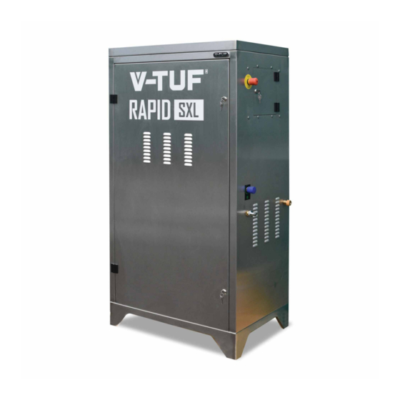
- Page 1 RAPIDSXL STAINLESS STEEL CABINET PRESSURE WASHERS Please read this manual before using the RAPIDSXL All Errors & Omissions Excused – Speci cation May Change Without Notice – Please Refer To www.v-tuf.co.uk For the Latest Version...
- Page 2 HOT WATER CABINET NOTES FOR THE CONSULTATIONS OF THE MANUAL This manual contains the information and anything else considered necessary for the knowledge, good use and normal maintenance of the HOT WATER CABINET hot water pressure washer, herein- after also referred to as machine or pressure washer, manufactured by the Constructor, hereinafter also referred to as Manufacturer.
- Page 3 MAIN WARNINGS FOR MACHINE USE It is mandatory to read this Use and Maintenance Instruction Manual before carry- ing out any work on the machine: its initial operation by unqualified persons could cause serious injuries to people and damage to property. All maintenance, adjustment and replacement operations described in this Use and Maintenance Instruction Manual must only be carried out after the machine has been stopped.
- Page 4 NOTE IN THE NEXT CHAPTERS, AT THE END OF THE PARAGRAPH, SUITABLE “CAUTION” NOTICES WILL BE LISTED REGARDING THE SPECIFIC RISKS APPLICABLE TO THE CHAPTER. THIS DOES NOT EXEMPT YOU, HOWEVER, FROM CONSIDERING ALL THE MAIN WARNINGS DESCRIBED ABOVE APPLICABLE. IMPORTANT NOTE PLEASE NOTE THAT THE USER IS REQUIRED, IN ACCORDANCE WITH ITALIAN LEGISLATIVE DECREE NO.
-
Page 5: Table Of Contents
INSTRUCTION MANUAL TABLE OF CONTENTS CHAPTER 1 - General information on the instruction manual.......8 1.1 Introduction ....................8 1.2 Standards of reference.................8 1.3 Compliance with legislation................9 1.4 Declaration of absence of harmful substances ..........9 1.5 Purpose of the document................9 1.6 Marking data and machine identification plate..........10 1.7 Use and storage of the Manual..............10 1.8 Documents accompanying this Manual ............11 1.9 User information ..................11... - Page 6 CHAPTER 10 - Connections to external energy sources........23 10.1 Electrical connection.................23 10.2 Water connection..................24 CHAPTER 11 - Control parts................25 11.1 Control station..................25 11.2 Control devices ..................26 11.2.1 control panel ................26 CHAPTER 12 - Preparing the machine for use ............27 12.1 Gun connection..................27 12.2 Connecting the high-pressure hose to the pressure washer......28 CHAPTER 13 - USE OF THE MACHINE..............29 13.1 Description of the operating cycle...............29...
-
Page 7: Chapter 1 - General Information On The Instruction Manual
CHAPTER 1 - GENERAL INFORMATION ON THE INSTRUCTION MANUAL 1.1 INTRODUCTION This manual will help you get to know your machine and use it correctly, so please read it carefully before using it.Each machine is sold with its own Use and Maintenance Manual. The user is respon- sible for the management of this manual throughout the life of the machine and will only dispose of it if it is destroyed.The manufacturer shall not be liable for any tampering with this manual or for any changes made to the machine by the user after delivery which are not covered in this... -
Page 8: Compliance With Legislation
1.2.1 UK MARKET COMPLIANCE The machine complies with current UK legislation. By affixing the UKCA mark, you assume full responsibility for the product's compliance with the requirements of the relevant legislation. The UKCA mark is only used to demonstrate that the product complies with UK legislation. The UKCA mark is only affixed to the product by the manufacturer or authorised representative (where permitted by legislation);... -
Page 9: Marking Data And Machine Identification Plate
1.6 MARKING DATA AND MACHINE IDENTIFICATION PLATE The nameplate on the machine shows the manufacturer's data, the model, the serial number and the year of construction. For any communication regarding the machine (problems encountered, warranty work, spare parts, etc.) always refer to this and the data contained therein. In addition, any warning signs attached to the machine must not be removed for any reason whatsoever and must be strictly observed. -
Page 10: Documents Accompanying This Manual
1.8 DOCUMENTS ACCOMPANYING THIS MANUAL The machine is supplied complete with: − EC' declaration of conformity of the machine; − Instruction manual for the installation, use and maintenance of the machine; 1.9 USER INFORMATION This manual reflects the current state of the art of the machine and cannot be considered to be a guide inadequate only because it has been updated on the basis of new experience;... -
Page 11: Target Audience
1.9.2 TARGET AUDIENCE This manual is the basic tool for personnel who, in various capacities, deal with the machine in various tasks, such as: • Transport and machine handling workers. • Pressure washer operators. • Maintenance operators. • Final demolition workers. Before proceeding with the various operations, the persons listed above must have carefully read and memorised this manual. -
Page 12: Chapter 2 - General Machine Description
CHAPTER 2 - GENERAL MACHINE DESCRIPTION The HOT WATER CABINET hot water pressure washer referred to in this manual is primarily designed to pump water at pressures of up to 250 bar (only some models). The hot water pressure washer is intended exclusively for cleaning and washing with hot or cold water of objects or surfaces that are suitable for mechanical treatment by the high-pressure water jet and the possible chemical action of detergents. -
Page 13: Description Of The Machine Elements
2.1 DESCRIPTION OF THE MACHINE ELEMENTS The pressure washer consists of the following main components (see figures in this section): 1. Steel cabinet, 2. Steel supporting frame 3. 43 l diesel tank o 3a breather cap for diesel tank (anti-pressure tank) 4. - Page 14 13.14...
-
Page 15: Construction Technology
2.2 CONSTRUCTION TECHNOLOGY The products are always up-to-date, both in design and technology, to make the use of high pressure washers safer, simpler and more reliable, both from the user's point of view and from the technical assistance point of view. VTUF iDPS (Digital Protection System) means: Delayed Auto stop (30 second delay stop motor with immediate start) –... -
Page 16: Chapter 3 - Machine Safety And Protection
CHAPTER 3 - MACHINE SAFETY AND PROTECTION 3.1 SAFETY RULES FOR ELECTRICAL RISK ▪ Do not use the machine outdoors in the rain. ▪ If, despite all the precautions taken, the cable is damaged, do not carry out temporary repairs. A new cable is much cheaper than repairing the damage caused by a possible electric shock, not to mention the danger that a defective cable would pose to people and animals. -
Page 17: Safety Rules For Mechanical Risk
3.3 SAFETY RULES FOR MECHANICAL RISK ▪ Do not put your hands in front of the wand; high-pressure nozzles can be extremely dangerous when used improperly ▪ When the work is completed, after stopping the machine, release the residual pressure in the delivery pipe and in the pump by operating the gun lever. - Page 18 DESCRIPTION Pictograms on the control panel providing safety instructions on the risks involved in using the pressure jet ▪ Generic HAZARD HAZARD EXPLANATION Read the manual before using the machine ▪ HAZARD of cutting, impact, abrasion, burns Do not direct the jet at people or animals Machine with fluid under pressure.
-
Page 19: Chapter 4 - Residual Risks
CHAPTER 4 - RESIDUAL RISKS Despite the safety precautions taken by the manufacturer during the design and production phases, during the normal production cycle the machine still presents certain risks that are considered residual. This chapter lists the residual risks and the rules to be observed in order to avoid situations that are hazardous for the operator, the machine and the surrounding environment due to the presence of these residual risks. -
Page 20: Chapter 5 - Personal Protective Equipment
CHAPTER 5 - PERSONAL PROTECTIVE EQUIPMENT When operating the machine or during maintenance, personal protective equipment must be worn, such as: • Safety overalls; • Protective gloves against thermal and mechanical hazards; • Eye protection; • Face shield; • Non-slip shoes; •... -
Page 21: Use In Closed Environments
6.1 USE IN CLOSED ENVIRONMENTS If the machine is located in an enclosed area, the adapter for the smoke exhaust chimney (code 5000030) must be fitted. If the machine is located in an enclosed area, it must be well ventilated and it must be ensured that exhaust ATTENTION The diameter (Z) of the chimney (2) must not be smaller than that of the adapter (1). -
Page 22: Contraindication And Hazards Due To Unintended Or Misuse
6.3 CONTRAINDICATION AND HAZARDS DUE TO UNINTENDED OR MISUSE 1. Any operation not mentioned in this manual is considered to be an improper use of the machine which could cause damage to persons and/or property. 2. The machine has not been built to work in an explosive environment, SO IT IS ABSOLUTELY FORBIDDEN TO USE THE MACHINE IN AN EXPLOSIVE ATMOSPHERE. -
Page 23: Chapter 7 - Technical Data
CHAPTER 7 - TECHNICAL DATA 7.1 ENVIRONMENTAL REQUIREMENTS The HOT WATER CABINET hot water pressure washer has been designed and manufactured to be used in the following environmental conditions. • Maximum temperature +90°C • Minimum temperature +1°C • Relative humidity 80% 7.2 DIMENSIONS AND TECHNICAL DATA Line Mono-Phase... -
Page 24: Chapter 8 - Commissioning The Machine
CHAPTER 8 - COMMISSIONING THE MACHINE 8.1 PREVENTIVE CHECKS AFTER RECEIPT Upon receipt of the goods, check the condition of the package; if any damage is found, refrain from any installation procedure and notify the carrier and supplier immediately. Ascertain the good condition of the package, proceed to unpack the goods and check that the delivery is complete (check correspondence with the delivery note);... -
Page 25: Chapter 9 - Handling And Installation Of The Machine
CHAPTER 9 - HANDLING AND INSTALLATION OF THE MACHINE 9.1 PRELIMINARY OPERATIONS The machine was tested in the manufacturer's factory to verify the correct functioning of all components according to the specifications in force. No preliminary operations are required. 9.2 LIFTING If the machine is to be transported, it must be secured by means of straps, ropes or other suitable means in a stable and safe manner to prevent accidental movement from causing damage to persons or property as well as to the machine itself. -
Page 26: Chapter 10 - Connections To External Energy Sources
CHAPTER 10 - CONNECTIONS TO EXTERNAL ENERGY SOURCES 10.1 ELECTRICAL CONNECTION Electricity for the operation of all electrical components on the machine must be supplied by means of a cable connected to the general electrical system. It is compulsory to connect the machine to an earthing system with a resistance value that guarantees a contact voltage of no more than 25V. -
Page 27: Water Connection
10.2 WATER CONNECTION On the rear of the machine there is a water inlet connection. Connect a water supply hose (not supplied) to the inlet fitting (3 in the figure) and the other end of the hose to the tap (4), which must guarantee a minimum flow rate equal to that of the pump THE HYDRAULIC CIRCUIT DIAGRAM IS ATTACHED TO THE DOCUMENTATION SUPPLIED WITH THE MACHINE. -
Page 28: Chapter 11 - Control Parts
CHAPTER 11 - CONTROL PARTS 11.1 CONTROL STATION The control station is the place where the operator must be to manage the work cycle and supervise the machine's operation. The machine is equipped with: ▪ NO. 1 COMMAND AND CONTROL PANEL (A), on which the machine's parameters and work programmes can be set;... -
Page 29: Control Devices
11.2 CONTROL DEVICES 11.2.1 CONTROL PANEL EFERENCE Pump engine start light switch (in) ONTROL PART Controls the switching on of the pump engine and the switching on of the corresponding ESCRIPTION warning light EFERENCE Burner ignition light switch (br) ONTROL PART Controls the ignition of the burner and the switching on of the relevant indicator light ESCRIPTION EFERENCE... -
Page 30: Chapter 12 - Preparing The Machine For Use
EFERENCE Thermostat (tr) ONTROL PART Thermostat to select the water temperature. ESCRIPTION EFERENCE Burner flame failure warning light (where present photocell for control) ONTROL PART Lights up to signal burner flame failure ESCRIPTION EFERENCE Photocell reset button ONTROL PART Button to reset the photocell ESCRIPTION CHAPTER 12 - PREPARING THE MACHINE FOR USE After positioning the machine in the work area and making the connections to external energy sources... -
Page 31: Connecting The High-Pressure Hose To The Pressure Washer
12.2 CONNECTING THE HIGH-PRESSURE HOSE TO THE PRESSURE WASHER Now connect the wand to the A.P. (high pressure) hose (A) Fit the sheath (B) to protect the hydraulic connection and avoid contact burns. The A.P. (high pressure) pump is supplied already filled with lubricating oil. ATTENTION The adjustment operations described in this chapter must be carried out ONLY by qualified and authorised personnel. -
Page 32: Chapter 13 - Use Of The Machine
CHAPTER 13 - USE OF THE MACHINE 13.1 DESCRIPTION OF THE OPERATING CYCLE 13.1.1 COLD WATER OPERATION 1. Check that the line indicator light(c) is lit and that there is voltage inside the machine. b (Br a (in) Open the tap for drawing water from the water mains (3) and then start the pump engine unit using the switch (a) located on the electrical control panel. -
Page 33: Hot Water Operation
13.1.2 HOT WATER OPERATION Check that the diesel tank is full (1); if not, fill it up using diesel fuel only b (Br a (in) • Repeat step 1 and step 2 of cold water operation (previous paragraph). • Check that the thermostat(tr) is set to 0°C. •... - Page 34 TROUBLE SHOOTING GUIDE ATTENTION During operation, no-one other than the operators in charge must stand near the machine or, worse still, intervene on it. The protections have been designed by the manufacturer in order to safeguard the safety of the operators while carrying out their tasks. During operation, the guards must not be removed for any reason.
-
Page 35: Use With Chemical Product
13.1.3 USE WITH CHEMICAL PRODUCT With the machine switched on, without operating the gun, turn the black adjustable head anti-clockwise to draw in the detergent. The machine dispenses detergent at high pressure, and can be adjusted by means of the blue detergent knob (D-HP) on the front of the machine D-HP Figure 4.7... - Page 36 • Important tips To protect the environment, we recommend using only approved detergents, observing the recommen- dations for use and dosage on the packaging labels, using detergent sparingly and remembering that unsuitable detergents, as well as causing damage to the environment, can also damage the pressure washer and the objects to be cleaned.
-
Page 37: Contraindications To Using The Machine
13.2 CONTRAINDICATIONS TO USING THE MACHINE Full compliance with the Machinery Directive 2006/42 EC and the efforts made by our engineers during the design phase have resulted in a machine that can be placed at the highest safety level for its category. -
Page 38: Chapter 14 - Maintenance
CHAPTER 14 - MAINTENANCE Maintenance is a set of periodic and predefined operations aimed at maintaining the functionality of the machine in all its aspects, as a result of the wear and tear inherent in its use. The various routine maintenance operations are described below. Please note that lower operating costs and a long service life of the machine depend on continuous compliance with this manual. -
Page 39: Adjusting The Ignition Electrodes
14.4 ADJUSTING THE IGNITION ELECTRODES OPERATION CARRIED OUT ONLY BY SERVICE CENTER For optimum operation of the machine, it must be checked that the ignition electrodes are always arranged correctly, as shown in the diagram. 14.4.1 CONTROL OF THE HEIGHT IN RELATION TO THE PLANE OF THE DIESEL NOZZLE HEAD OPERATION CARRIED OUT ONLY BY SERVICE CENTER Place the control rod on the diesel nozzle head, as shown in figure, and check that the two electrodes do not cross the upper wire. -
Page 40: Electrode Distance Control
14.4.2 ELECTRODE DISTANCE CONTROL OPERATION CARRIED OUT ONLY BY SERVICE CENTER Place the control rod on the head of the diesel nozzle, as shown in figure 2, and check that the two electrodes are in contact with the surfaces of the rod. 14.4.3 CHECKING THE DISTANCE BETWEEN THE ELECTRODES AND THE CENTRE OF THE DIESEL NOZZLE HEAD OPERATION CARRIED OUT ONLY BY SERVICE CENTER... -
Page 41: Troubleshooting
14.5 TROUBLESHOOTING The tables below list the main malfunctions, with their causes and recommended remedies, that the machine may present during operation. Any work required must only be carried out by experienced and qualified operators after having read this manual. PROBLEM CAUSE SOLUTION... - Page 42 PROBLEM CAUSE SOLUTION Pressure drop. Worn suction and/or discharge Replace the valves. valves. Presence of foreign bodies in Check and clean. the valves impairing operation. Air intake. Check the intake ducts. Worn gaskets. Replacing seals Regular pressure at Worn water nozzle . Replace the nozzle.
- Page 43 PROBLEM CAUSE SOLUTION Presence of water in the Worn crankcase side seal ring. Replace the sealing ring. pump oil High percentage of humidity in the Change the oil twice as often as air. prescribed. Gaskets completely worn. Replace the seals. Noise Air intake.
-
Page 44: Chapter 15 - Disposal
CHAPTER 15 - DISPOSAL 15.1 PRESSURE WASHER DISPOSAL (DEMOLITION OF THE MACHINE) If you decide to scrap the machine, to prevent it from posing an hazard to people and the environment, it is necessary: • disconnect the machine from the mains power supply and from the water supply network •... -
Page 45: Chapter 17 - Sound Emission
CHAPTER 17 - SOUND EMISSION The Leq equivalent level averaged over multiple processing cycles (including footwear change stages) was measured with Class 1 precision sound level meter as set out in IEC standards with fast-slow reading constant, both from the position where the operator is, and in positions surrounding the machine being considered. -
Page 46: Chapter 18 - Hand-Arm Vibrations
CHAPTER 18 - HAND-ARM VIBRATIONS The level of vibration transmitted to the hand-arm system during the work phase via the wand handle is below the warning limit and is equal to aw = 1.46 m/sec (as shown in the graph above). -
Page 47: Chapter 19 - Summary Of The Main Warnings
CHAPTER 19 - SUMMARY OF THE MAIN WARNINGS • The safety devices have been designed by the manufacturer to safeguard the operator's safety while performing his tasks. The devices must not be tampered with under any circumstances during operation. • Work on the switchboard may only be carried out by qualified electricians. •... -
Page 48: Personal Data
20.2 PERSONAL DATA An exact description of the model, serial number and any installed accessories will facilitate quick and effective responses from the manufacturer or service centre. Always state the type, model and serial number of the machine whenever you contact the service centre. As a reminder, we suggest that you enter the machine data in this box. -
Page 49: A - Electrical System Diagram
TTACHMENT LECTRICAL SYSTEM DIAGRAM THREE-PHASE 400V WIRING DIAGRAM... - Page 50 WIRING DIAGRAM WITH THREE-PHASE 400V RESISTOR BOARD...
-
Page 51: B - Hydraulic System Diagram
TTACHMENT HYDRAULIC SYSTEM DIAGRAM Key: = water tap T.a. = water suction hose = filter = detergent filter T.a.d. = detergent suction hose = water pump T.m. = discharge pipe = boiler T.a.p. = high pressure water outlet pipe = wand... - Page 52 PUMP DIAGRAM FOR RAPIDSXL110 & RAPIDSXL240 MODELS Super Series Pump XHDM300SS 12 litres/min 200 bar VTPKIT 134 XHDM300SS XHDM350SS VTPKIT 135 VTPKIT 137 VTPKIT 2 XHDM300SS LUBRICATION OF THE PUMP We recommend: VTUF PL100 – OIL CAPACITY 0.42 kg You should change the oil after the rst 50 hours of use, and after each...
- Page 53 PUMP DIAGRAM FOR RAPIDSXL415 Super Series Pump XHDM400SS 15 litres/min 200 bar VTPKIT 206 VTPKIT 28 VTPKIT 208 VTPKIT 2 XHDM400SS XHDM400SS 200 Bar | 15 L/min | 1450 rpm LUBRICATION OF THE PUMP We recommend: VTUF PL500 – Pressure Lube Pump Oil - Fill Pump To Halfway You should change the oil after the rst 50 hours of use, and after each subsequent 500 hours of operation.
- Page 54 Pump Diagram for RAPIDSXL415-21 Super Series Pump XHDM450SS 21 litres/min 200 bar VTPKIT 206 VTPKIT 28 VTPKIT 208 VTPKIT 2 XHDM450SS XHDM450SS 200 Bar | 21 L/min | 1450 rpm LUBRICATION OF THE PUMP We recommend: VTUF PL500 – Pressure Lube Pump Oil - Fill Pump To Halfway You should change the oil after the rst 50 hours of use, and after each subsequent 500 hours of operation.
- Page 56 Manufacturer V-TUF, Unit 5 Chris Sharp Building, Till Bridge Lane, Scampton, Lincoln, LN1 2SX UK Authorised Representative Established in the EU Flexrep EU OÜ, Attn: E-Residency Hub, Ahtri tn 12, 10151 Tallinn, Estonia...
Need help?
Do you have a question about the RAPIDSXL110 and is the answer not in the manual?
Questions and answers