Table of Contents
Advertisement
3156453
Rev. N
01/18
18-3-645 4th Edition
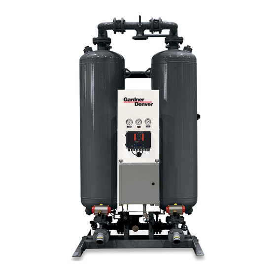
INSTRUCTION MANUAL
DHP SERIES
RATED
MODELS
FLOW
DHP300
300 SCFM
DHP400
400 SCFM
DHP500
500 SCFM
DHP600
600 SCFM
DHP750
750 SCFM
DHP900
900 SCFM
DHP1050
1050 SCFM
DHP1300
1300 SCFM
DHP1500
1500 SCFM
DHP1800
1800 SCFM
DHP2200
2200 SCFM
DHP2600
2600 SCFM
DHP3200
3200 SCFM
Contents
1.0 General Safety Information ........................... 2
2.0 Receiving, Storing, and Moving ..................... 2
3.0 Description .................................................... 3
4.0 Installation ..................................................... 3
5.0 Instrumentation .............................................. 8
6.0 Operation ....................................................... 11
7.0 Maintenance .................................................. 28
8.0 Troubleshooting ............................................. 30
9.0 Purge Information .......................................... 33
DRAWINGS
P&ID Schematic: Models 300 through 600........... 34
P&ID Schematic: Models 750 through 3200......... 36
Electrical Schematic - 460VAC, 3 phase .............. 38
Electrical Schematic - 575VAC, 3 phase .............. 39
Models 300 through 600 ........................................ 40
Models 750 through 1800 ...................................... 42
Models 2200 through 3200 .................................... 44
WARRANTY .......................................................... 48
MODEL
REFERENCE
300
400
500
600
750
900
1050
1300
1500
1800
2200
2600
3200
For Sales and Service: (800) 883-2477
Or visit Sales and Service at www.gardnerdenverproducts.com
HEATED PURGE
DESICCANT
COMPRESSED
AIR DRYERS
Advertisement
Table of Contents

Related Manuals for Gardner Denver DHP Series


Summary of Contents for Gardner Denver DHP Series
-
Page 1: Table Of Contents
3156453 Rev. N 01/18 18-3-645 4th Edition INSTRUCTION MANUAL DHP SERIES RATED MODEL MODELS FLOW REFERENCE DHP300 300 SCFM DHP400 400 SCFM DHP500 500 SCFM DHP600 600 SCFM DHP750 750 SCFM DHP900 900 SCFM DHP1050 1050 SCFM 1050 DHP1300 1300 SCFM... -
Page 2: General Safety Information
CAUTION—Hazard or unsafe practice which could result 1.0 General Safety Information in minor injury or in product or property damage. The dryer data plate, attached to the electrical control box, This equipment is designed and built with safety as a prime contains critical safety and identification information. -
Page 3: Description
after tower change over. The tower is then repres- 3.0 Description surized to full line pressure. This prevents desiccant bed movement and downstream pressure loss when 3.1 Function the tower goes back on-line. Externally Heated Purge Air dryers are an economical and reliable way to dry compressed air to dew points below the freezing point of water. - Page 4 Compressor Aftercooler Separator Receiver Prefilters Desiccant Dryer Afterfilter Receiver Figure 1 Typical System Configuration 4.3 Location and Clearance CAUTION — Do not hydrostatically test the piping with the dryer in the system. The desiccant will be Install the dryer on a level pad. Ensure the dryer is level damaged if saturated with water.
- Page 5 NOTE: Before turning high voltage on to the dryer, an 3. Refer to Table 1 for desiccant quantity per tower. ohmic test should be performed on the heater elements When using Table 1 you will find the desiccant quanti- to insure they are dry before proceeding with start-up. ties listed in layers.
- Page 6 Dimensions and Connections – Dryer Only Figure 2 (continued on next page) (For construction purposes, contact factory to request certified drawings when mounted filters are included with order)
- Page 7 Dimensions and Connections Figure 2 (continued from previous page)
-
Page 8: Instrumentation
5.5 Venturi Blower 5.0 Instrumentation This precision engineered venturi blower uses ambient air to boost the bed regeneration flow-through capacity. The following instrumentation helps in monitoring dryer It is included with the Energy Management System. operation and performance. Instruments which are avail- able as options are so noted. - Page 9 PURGE INLET CHECK VALVE TOP VIEW HEATER TEMP THERMOCOUPLE (CENTER END IN PIPE) HOT PIPE INSULATION (OPPOSITE SIDE) (OPTIONAL) HEATER OVERTEMP RTD PURGE ADJUSTING VALVE (REMOVE HANDLE AFTER PURGE SAVER INITIAL DRYER TEST) INTAKE FILTER (OPTIONAL) PURGE SAVER INTAKE SHUT-OFF VALVE (OPTIONAL) ASME CODE TAG PURGE SAVER...
- Page 10 TOP VIEW HOT PIPE INSULATION (OPTIONAL) HEATER TEMP THERMOCOUPLE (CENTER END IN PIPE) (OPPOSITE SIDE) PURGE INLET CHECK VALVE HEATER OVERTEMP RTD PURGE SHUT-OFF VALVE PURGE ADJUSTING VALVE (REMOVE HANDLE AFTER INITIAL DRYER TEST) PURGE SAVER INTAKE FILTER (OPTIONAL) ASME CODE TAG PURGE SAVER INTAKE SHUT-OFF VALVE (OPTIONAL)
-
Page 11: Operation
haust Valve (D). The Heater is de-energized when 6.0 Operation the Right Chamber temperature sensor detects desiccant bed heating is complete. Purge flow will 6.1 Controls continue to cool the right tower desiccant bed while A solid-state controller controls valve and heater opera- “recovered”... - Page 12 Figure 4 Figure 5 Fixed Cycle Operation Demand Cycle Operation with Venturi Blower Left Chamber Drying – Right Chamber Regenerating Left Chamber Drying – Right Chamber Regenerating Next, Purge Supply Valve (E) and Right Tower Purge heated purge air then flows through the Left Purge Exhaust Valve (D) are opened, and the Heater is Check Valve, down through the left tower, and exits turned on.
- Page 13 6.4 Control Board Jumpers 7. JP7 – Download Language Text Jumper JP7 is factory installed in the OFF position In the upper left hand corner of the control board there to disable Language Text download. The jumper is are eight two-pin jumpers labeled JP1 through JP8. Only installed in the ON position to allow for language text six of the eight jumper pairs are utilized.
- Page 14 Filter Service / Left Tower Pressure Maintenance LED Switch LED: On=Tower Pressurized Filter Service / Maintenance LED Left Tower Drying LED Right Tower Pressure Left Purge Valve LED Switch LED: On=valve open On=Tower pressurized Off=valve closed Left Inlet Valve LED Right Tower Drying LED On=valve open Off=valve closed...
- Page 15 b. SEVERE Service Intervals are: Screen 7: Set Point for Dew Point Demand Control i. 2000 hours for filters (This feature is only active when JP3 is “on”) ii. 4000 hours for desiccant DPNT CNTL SETPT iii. 4000 hours for valves ±XX°C ±XXX°F 2.
- Page 16 6.5.5 Setup Mode 2. When finished, press to acknowledge the selec- 1. Press and hold for 3 seconds to enter Setup tion and scroll to the pressure set point screen. Mode. 3. Press to increment the setting to the desired 2.
- Page 17 5. When an alarm condition has not been corrected 8. The dryer is equipped with RTD temperature and the “alarm reset” button is pressed, the alarm sensors. There are out of range alarms for each. will not clear except as follows: a.
- Page 18 ALARM MESSAGES LEFT TOWER ALARMS RIGHT TOWER ALARMS OTHER ALARMS ALARM LEFT TOWER ALARM RIGHT TWR ALARM COOLING DRYING DRYING HEATER HIGH TEMP LOW PRESSURE LOW PRESSURE ALARM LEFT TOWER ALARM RIGHT TWR ALARM HEATER REGENERATING REGENERATING OVER-TEMPERATURE HIGH PRESSURE HIGH PRESSURE ALARM LEFT TOWER ALARM RIGHT TWR...
- Page 19 11. Heater Over-Temperature a. RTD3 is used to detect Heater Over-Tempera- ture. b. Alarms anytime that the Heater temperature exceeds 650°F (343°C). c. On alarm condition, de-energize heat cycle, stop cycle sequence, display local alarm and de-ener- gize common alarm relay. d.
- Page 20 6.5.7 Display Mode Service Due Messages 1. Display Mode is active when the user exits Program 14. There are two service levels (normal and severe) Mode or Setup Mode and no alarms are active (un- as described in Program Mode. Each service level less MANUAL CYCLE was selected in Setup Mode).
- Page 21 DRYER STATUS SCREENS LEFT TOWER DRYING RIGHT TOWER DRYING LT DRYING LT DEPRESSURIZE RT DEPRESSURIZE RT DRYING LT DRYING LT HEATING RT HEATING RT DRYING LT DRYING LT COOLING RT COOLING RT DRYING LT DRYING LT REPRESSURIZE RT REPRESSURIZE RT DRYING LT DRYING LT HOLDING RT HOLDING...
- Page 22 6.5.8 Test Mode 5. To exit Test Mode: 1. Test Mode is active when the user exits Program a. Press and hold for 3 seconds to exit Test Mode after selecting operation in MANUAL CYCLE. Mode. The display switches to Screen 2 of Setup Mode.
- Page 23 TEST MODE SCREENS Screen 1: Step 1 Screen 7: Step 7 TEST1: LT DRYING TEST7: RT DRYING XX°C XXX°F XX°C XXX°F Screen 2: Step 2 Screen 8: Step 8 TEST2: DEPR RT TEST8: DEPR LT XX°C XXX°F XX°C XXX°F NOTE: Sequence step will not advance to HEAT until NOTE: Sequence step will not advance to HEAT until tower has fully depressurized.
- Page 24 6.6 Start-up 6.7.5 Check Mufflers For Back pressure (models 300 through 750) 6.6.1 Controller Settings Excessive back pressure may result due to the Set or verify settings on Controller. Detailed operational accumulation of desiccant fines (dust) in the muffler points are presented in section 6.5 cartridges.
- Page 25 Two mainline outlet and two smaller purge line check 6.9.1.2 On restoration of power – valves are installed in the upper piping to control the flow 1. If power is lost when the off-line tower is in either of outlet and purge air. Check valve sticking will result in the HEAT or COOL step, the off-line tower will have excessive air discharge through a muffler.
- Page 26 6.10 Using the RS-232 Port xxxx ASCII representation of the filter time to service (hours) The RS-232 port is used to monitor dryer operation from a host computer. xxxx ASCII representation of the desiccant time to RS-232 connections are made at the 3-pin connector service (hours) labeled J3 and located at the upper left-hand corner of the control board.
- Page 27 Example: If jumper 8, 5, and 1 are installed, a value of 128+16+1 = 145 is returned To decode, the algorithm: · If (number >= 128) è jumper 8 = on · number = number - 128 · If (number >= 64) è jumper = on ·...
-
Page 28: Maintenance
e. Utilizing an appropriate sized funnel, fill each 7.0 Maintenance desiccant tower as follows: 1) Install the required quantity of activated alu- WARNING - This equipment is a pressure-containing mina in layer 1 of each tower. device. Depressurize before servicing. 2) Level layer 1 and each subsequent layer of NOTE: The Dryer Controller is equipped with Service desiccant as added to each tower. - Page 29 2. Procedure for element replacement a. Isolate dryer from air supply b. Depressurize dryer by running dryer and allowing system pressure to purge to atmosphere. Loss of pilot pressure will eventually prevent purge/ repressurization valves from opening. Remaining pressure can be vented to atmosphere through the manual drain on the pilot air filter.
-
Page 30: Troubleshooting
8.0 Troubleshooting WARNING - A POTENTIAL ELECTRICAL SHOCK HAZARD EXISTS. Some of the troubleshooting checks may require gaining access to the dryer’s electrical enclosure(s) while the power supply is energized and should be performed by a qualified electrical technician. WARNING - Before performing any electrical or mechanical repairs or maintenance, or removing or disassembling any component, be sure to de- energize and depressurize the dryer. - Page 31 SYMPTOM POSSIBLE CAUSE(S) CORRECTIVE ACTION High Pressure Alarm 1. Faulty regenerating tower pressure 1. Check pressure switch operation using tower pressure Left Tower or Right Tower Re- switch gauge for comparison. Replace switch if defective. generating 2. Regenerating tower Depressurization 2.
- Page 32 SYMPTOM POSSIBLE CAUSE(S) CORRECTIVE ACTION Outlet Dew Point Alarm 1. Inlet air flow higher than the sizing 1. Reduce inlet flow to sizing condition. Left Tower or Right Tower condition. 2. Liquids entering the dryer inlet. 2. Check the inlet air line for liquids. Inspect prefilter and drain valve.
-
Page 33: Purge Information
9.0 Purge Information NO PURGE WITH PURGE SAVER SAVER PURGE SET PURGE SET MODEL ORIFICE DIA. (IN) PRESSURE (PSIG) PRESSURE (PSIG) 7/32 9/32 5/16 11/32 1050 13/32 1300 29/64 1500 31/64 1800 17/32 2200 37/64 2600 3200 45/64... -
Page 34: P&Id Schematic: Models 300 Through 600
P&ID Schematic Models 300-600 (Contact factory to request certified drawings) DRY GAS OUTLET SET AT 55 PSIG (MODELS 400-600) SET AT 60 PSIG (MODEL 300) SET @ 165 PSIG DEWPOINTER OPTION SET @ 45 PSIG SET @ 20 PSIG FALLING OPTIONAL SET AT 100 PSIG... - Page 35 LEGEND ENERGY MANAGEMENT OPTION INLET VALVE (V1 LEFT, V2 RIGHT) PURGE EXHAUST VALVE (V3 LEFT, V4 RIGHT) ENERGY MANAGEMENT PILOT OPERATED VALVE PURGE CHECK VALVE (V5 LEFT, V6 RIGHT) ENERGY MANAGEMENT SENSOR (RTD4/HS1) OUTLET CHECK VALVE (V7 LEFT, V8 RIGHT) PURGE SAVER PURGE HEATER WITH INSULATION PURGE SAVER INTAKE SHUT-OFF VALVE...
-
Page 36: P&Id Schematic: Models 750 Through 3200
P&ID Schematic Models 750-3200 (Contact factory to request certified drawings) DRY GAS 1(A) (P1) OUTLET SET AT 55 PSIG 2(B) SOL 'E' (MODEL 750,1050-3200) SET AT 60 PSIG (MODEL 900) SET @ 165 PSIG DEWPOINTER OPTION SET @ 45 PSIG SET @ 20 PSIG FALLING... - Page 37 LEGEND INLET VALVE (V1 LEFT, V2 RIGHT) PURGE PRESSURE GAUGE FLOW CONTROL VALVE PURGE FLOW ORIFICE PURGE EXHAUST VALVE (V3 LEFT, V4 RIGHT) (NOT PROVIDED WITH PURGE SAVER) PURGE CHECK VALVE (V5 LEFT, V6 RIGHT) PURGE SHUTOFF VALVE OUTLET CHECK VALVE (V7 LEFT, V8 RIGHT) (MODELS 900 THROUGH 3200) DEPRESS SOLENOID VALVE (V9 LEFT, V10 RIGHT) PRESSURE REGULATOR...
-
Page 38: Electrical Schematic - 460Vac, 3 Phase
Electrical Schematic – 460VAC, 3 phase (Contact factory to request certified drawings) DETAIL A 1HTR (2-WIRE DEWPOINT TRANSMITTER) +12VDC CUSTOMER PROVIDED EXTERNALLY LOCATED 460VAC, 3 PHASE DEWPOINT (FOR FUSING SEE TABLE) TRANSMITTER + 4-20MA OUT 0.5 AMP NOTE: LOW TENSION VERIFY TRANSFORMER IS 0.5 AMP WIRED FOR THE VOLTAGE... -
Page 39: Electrical Schematic - 575Vac, 3 Phase
Electrical Schematic – 575VAC, 3 phase (Contact factory to request certified drawings) DETAIL A 1HTR (2-WIRE DEWPOINT TRANSMITTER) CUSTOMER PROVIDED +12VDC 575VAC, 3 PHASE EXTERNALLY LOCATED (FOR FUSING SEE TABLE) DEWPOINT TRANSMITTER SEE TABLE 1 + 4-20MA OUT 0.5 AMP NOTE: LOW TENSION VERIFY TRANSFORMER IS... -
Page 40: Replacement Parts Models 300 Through 600
Replacement Parts – Models 300 through 600 42 43 REAR VIEW RIGHT CHAMBER LEFT CHAMBER CONTROL ENCLOSURE HIGH TENSION ENCLOSURE FRONT VIEW SIDE VIEW (RIGHT CHAMBER REMOVED FOR CLARITY) Gardner Denver Inc. Phone: (800) 682-9868 Web: www.gardnerdenverproducts.com... - Page 41 1. Parts and Maintenance Kits are for standard builds only. Please contact the factory with your dryer serial number for assistance on identifying spare parts and maintenance kits for your specific unit. 2. All quantities for one dryer. 3. ID# correspond to P&ID legend (* Not identified in replacement part diagram and/or not assigned number on P&ID diagram.) Gardner Denver Inc. Phone: (800) 682-9868 Web: www.gardnerdenverproducts.com...
-
Page 42: Models 750 Through 1800
Replacement Parts – Models 750 through 1800 MODEL 750 1 1A REAR VIEW RIGHT CHAMBER LEFT CHAMBER CONTROL ENCLOSURE HIGH TENSION ENCLOSURE FRONT VIEW SIDE VIEW (RIGHT CHAMBER REMOVED FOR CLARITY) Gardner Denver Inc. Phone: (800) 682-9868 Web: www.gardnerdenverproducts.com... - Page 43 2. All quantities for one dryer. 3. ID# correspond to P&ID legend (* Not identified in replacement part diagram and/or not assigned number on P&ID diagram.) 4. N/A - Not Applicable to this Model Size Gardner Denver Inc. Phone: (800) 682-9868 Web: www.gardnerdenverproducts.com...
-
Page 44: Models 2200 Through 3200
Replacement Parts – Models 2200 through 3200 1 1A REAR VIEW RIGHT CHAMBER LEFT CHAMBER CONTROL ENCLOSURE HIGH TENSION ENCLOSURE FRONT VIEW SIDE VIEW (RIGHT CHAMBER REMOVED FOR CLARITY) Gardner Denver Inc. Phone: (800) 682-9868 Web: www.gardnerdenverproducts.com... - Page 45 1. Parts and Maintenance Kits are for standard builds only. Please contact the factory with your dryer serial number for assistance on identifying spare parts and maintenance kits for your specific unit. 2. All quantities for one dryer. 3. ID# correspond to P&ID legend (* Not identified in replacement part diagram and/or not assigned number on P&ID diagram.) Gardner Denver Inc. Phone: (800) 682-9868 Web: www.gardnerdenverproducts.com...
-
Page 48: Warranty
For additional information contact you local representative or Gardner Denver Inc. 1800 Gardner Expressway, Quincy, IL 62305 Telephone: (800) 682-9868 FAX: (217) 224-7814 Visit our Web Site: www.gardnerdenver.com © 2018 Gardner Denver, Inc. Printed in U.S.A 3156453 Rev. N 01/18 18-3-645 4th Edition...
Need help?
Do you have a question about the DHP Series and is the answer not in the manual?
Questions and answers