Gardner Denver RNC Series Instruction Manual
Refrigerated type compressed air dryers
Hide thumbs
Also See for RNC Series:
- Instruction manual (44 pages) ,
- Instruction manual (52 pages) ,
- Instruction manual (36 pages)
Table of Contents
Advertisement
5002737
Rev. B
02/09
18-2-670
RNC100-750 New Platform
INSTRUCTION MANUAL
RNC Series
Models: RNC100, RNC125, RNC150,
RNC200, RNC250, RNC300,
RNC400, RNC500, RNC600,
RNC750
CONTENTS
GENERAL SAFETY INFORMATION ........................... 2
RECEIVING, MOVING, AND UNPACKING .................. 2
1.0 INSTALLATION .................................................. 3
2.0 OPERATION ....................................................... 5
3.0 MAINTENANCE ................................................. 8
SIZING ................................................................... 10
ENGINEERING DATA (MODELS 100-250) ............... 11
ENGINEERING DATA (MODELS 300-750) ............... 12
WIRING DIAGRAM ............................................ 13-17
DIMENSIONS / WEIGHTS ....................................... 18
TROUBLESHOOTING GUIDE ................................... 19
PARTS LIST ............................................................ 21
WARRANTY ........................................................... 24
1st Edition
SERVICE DEPARTMENT: (724) 746-1100
33F......................39F
1C.......................4C
REFRIGERATED
TYPE
COMPRESSED
AIR DRYERS
Advertisement
Table of Contents

Related Manuals for Gardner Denver RNC Series


Summary of Contents for Gardner Denver RNC Series
-
Page 1: Table Of Contents
5002737 Rev. B 02/09 18-2-670 RNC100-750 New Platform 1st Edition INSTRUCTION MANUAL RNC Series Models: RNC100, RNC125, RNC150, RNC200, RNC250, RNC300, 33F......39F 1C.......4C RNC400, RNC500, RNC600, RNC750 CONTENTS REFRIGERATED GENERAL SAFETY INFORMATION ......2 TYPE RECEIVING, MOVING, AND UNPACKING ....2 1.0 INSTALLATION .......... -
Page 2: General Safety Information
GENERAL SAFETY INFORMATION RECEIVING, MOVING, AND UNPACKING 1. PRESSuRIzED DEVICES: A. RECEIVINg This equipment is a pressure containing This shipment has been thoroughly checked, packed and device. inspected before leaving our plant. It was received in good condition by the carrier and was so acknowledged. •... -
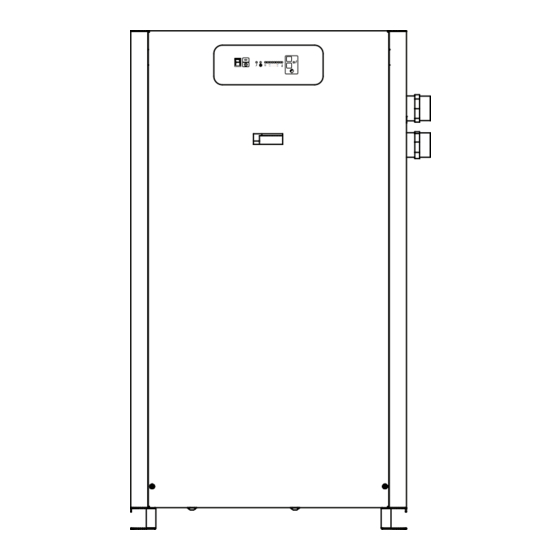
Page 3: Installation
IMPORTANT: Control Panel READ PRIOR TO STARTING THIS EQUIPMENT 1.0 INSTALLATION Moisture Separator Air Inlet 1.1 location Air Outlet For typical placement in a compressed air system, see Coalescing Filter (Option) drawing. Float Drain Air compressor intake–Locate air compressor so that (Standard) Electrical Entry contaminants potentially harmful to the dryer (e.g. - Page 4 1.3 Piping connections Model 100 with standard panel or optional I-Controller Level 1 ONLY: Air Inlet - Connect compressed air line from air source Separator has a knurled fitting with flexible drain tubing to air inlet. (Reference markings on dryer or, see callout attached.
-
Page 5: Operation
(Only Models with I-Controller Level 2) NOTE: The Timer Drain LED level has been pre-programmed at the factory for your specific RNC Series dryer. Programming is based upon a minimum of 100 psi saturated inlet air pressure and maximum energy efficiency. The drain open time is fixed at one second and a small amount of air will be exhausted with each cycle. - Page 6 2.6 I-Controller level 3 – Temperature Indica- Selector (Optional on models RNC200-RNC750) RNC Series dryers upgraded with the optional I-Controller Condensate Draining Level 3 include text messaging on the Vacuum Fluorescent (Flashes in Text Display (VFTD), Alert/Alarm condition display panel...
- Page 7 Green POWER ON light will illuminate. disassembly or serious injury may occur. VFTD will read “GARDNER DENVER IC3 (version)” Text NOTE: Discharge is at system pressure. Drain line should be display automatically sequences at 3 second intervals anchored.
-
Page 8: Maintenance
Condensate enters the reservoir (1) through the inlet 3.0 MAINTENANCE port. When the condensate level in the reservoir covers the capacitance sensor, an electronic signal is sent to the 3.1 Condenser coil solid state countdown processor. The processor delays Air-cooled - clean off accumulated dust and dirt monthly the opening of the solenoid valve for a given period or as necessary in dirty environments. - Page 9 3.3 Check separator daily to be sure automatic After making certain that o-ring inside top of bowl (and drain is discharging. on bayonet mount heads, wave spring) are in place, reassemble bowl to head. NOTE: Units with two stage filtration have two sets of drains. NOTE: Make certain o-ring is generously lubricated.
-
Page 10: Sizing
TABlE 2 SIZING Air capacity correction factors (Multipliers) Determining dryer capacity at actual operating conditions INLET COMPRESSED AIR CONDITIONS To determine the maximum inlet flow capacity of a dryer INLET TEMPERATURES INLET at various operating conditions, multiply the rated capacity PRESSURES from Table 1 by the multipliers shown in Table 2. -
Page 11: Engineering Data (Models 100-250)
ENGINEERING DATA (MODELS 100-250) Air System Data Rated Flow Capacity at 100°F, 100 psig Inlet, 100°F Ambient Temperature Maximum / Minimum Inlet Air Pressure (compressed air at inlet to dryer) 232 psig (16 barg) / 30 psig (2 barg) Maximum / Minimum Inlet Air Temperature (compressed air at inlet to dryer) 120°F (49°C) / 40°F (4°C) Maximum / Minimum Ambient Temperature Air-cooled: 110°F (43°C) / 40°F (4°C), Water-cooled: 130°F (54°C) / 40°F (4°C) -
Page 12: Engineering Data (Models 300-750)
ENGINEERING DATA (MODELS 300-750) Air System Data Rated Flow Capacity at 100°F, 100 psig Inlet, 100°F Ambient Temperature Maximum / Minimum Inlet Air Pressure (compressed air at inlet to dryer) 232 psig (16 barg) / 30 psig (2 barg) Maximum / Minimum Inlet Air Temperature (compressed air at inlet to dryer) 120°F (49°C) / 40°F (4°C) Maximum / Minimum Ambient Temperature Air-cooled: 110°F (43°C) / 40°F (4°C), Water-cooled: 130°F (54°C) / 40°F (4°C) -
Page 13: Wiring Diagram
Model 100 thru 150 (115 or 208-230V/60 Hz, 100 or 240V/50 Hz) DRAIN HARNESS BROWN CUSTOMER CONNECTION BLUE 120VAC GRN/YELLOW OPTIONAL DRAIN TO GROUND BAR GARDNER DENVER TEST IC1 LEVEL BOARD LINE NEUTRAL NOTES: JUMPER J5-1 TO J5-3 AND J5-5 TO J5-7 FOR 120 VAC THERMISTER THERMISTER DRAIN HARNESS... - Page 14 WIRING DIAGRAM I-Controller Level 2 Models 200 thru 600 (230-400-460V/3/50-60 Hz) CUSTOMER CONNECTION L1 L2 FROM LINE 21 COMPRESSOR HARNESS CONT 1 COMPRESSOR MTR1 REF SHEET 01 LINE 19 208V REF SHEET 02 LINE 18 230V 400V FAN 1 HARNESS 460V 575V FPS 1...
- Page 15 WIRING DIAGRAM I-Controller Level 2 Model 750 (230-400-460V/3/50-60 Hz) CUSTOMER CONNECTION FROM LINE 21 L1 L2 DISCONNECT COMPRESSOR HARNESS CONT 1 COMPRESSOR MTR1 REF SHEET 01 LINE 20 208V REF SHEET 02 LINE 12 230V 400V FAN 1 HARNESS 460V 575V FPS 1 FACTORY SET TO 460V...
- Page 16 WIRING DIAGRAM I-Controller Level 3 Models 200 thru 600 (230-400-460V/3/50-60 Hz) CUSTOMER CONNECTION FROM LINE 21 L1 L2 L3 TB1 L1 L2 L3 COMPRESSOR HARNESS CONT 1 MTR1 COMPRESSOR H4 H3 H2 H1 208V REF SHEET 01 LINE 20 230V REF SHEET 02 LINE 10 FAN 1 HARNESS 400V...
- Page 17 WIRING DIAGRAM I-Controller Level 3 Model 750 (230-400-460/3/50-60 Hz) CUSTOMER CONNECTION FROM LINE 21 TB1 L1 DISCONNECT COMPRESSOR HARNESS CONT 1 MTR1 COMPRESSOR H4 H3 REF SHEET 01 LINE 20 208V 230V 400V FAN 1 HARNESS 460V FPS 1 FACTORY SET TO 460V MTR2 FAN 1 (4 Terminal Blocks)
-
Page 18: Dimensions / Weights
DIMENSIONS / WEIGHTS Dimensions, inches (mm) Model 37.56 (954) 37.56 (954) 37.56 (954) 38.60 (980) 38.60 (980) 45.38 (1153) 45.38 (1153) 58.06 (1475) 58.06 (1475) 58.06 (1475) 25.62 (651) 25.62 (651) 25.62 (651) 32.15 (817) 32.15 (817) 32.15 (817) 32.15 (817) 32.15 (817) 32.15 (817) 32.15 (817) -
Page 19: Troubleshooting Guide
TROUBLESHOOTING GUIDE SYMPTOM POSSIBLE CAUSE(S) CORRECTIVE ACTION A) Water downstream of dryer. 1. Residual free moisture remaining in Blow out system with dry air. downstream pipelines. 2. Air bypass system is open. Check valve positions. 3. Inlet and Outlet connections are reversed. Check for correct connection. - Page 20 I-CONTROllER lEVEl 3 Alert/Alarm Condition Indicators TABlE 2 I-Controller Level 3 Alert/Alarm Fault Status Indicator Guide Text Window Fault Condition Panel Lights Process Diagram LEDs* Audible Alarm (1) Fault Event Alarm Alert / Compressor Thermometer Gauge Separator /Filter Contacts N/O Contacts N/C Notification Identification...
-
Page 21: Parts List
PARTS LIST 115/1/60 115/1/60 115/1/60 PARTS DESCRIPTION 208-230/1/60 220-240/1/50 208-230/1/60 220-240/1/50 208-230/1/60 220-240/1/50 100/1/60 100/1/60 100/1/60 Condensing Unit Assembly G5002001 G5002002 G5002003 G5002004 G5002005 G5002006 G5002004 G5002005 G5002006 Compressor (Only) G5002243 G5002250 G5002256 G3221302 G3210940 G3232808 G3221302 G3210940 G3232808 Overload G5002244 G5002251 G5002257... - Page 22 NOTES...
- Page 23 NOTES...
-
Page 24: Warranty
IS RETURNED TO THE FACTORY OR IN-WARRANTY REPAIRS ARE MADE. SERVICE DEPARTMENT: (724) 746-1100 For additional information contact your local representative or Gardner Denver Compressor and Pump Division, 1800 Gardner Expressway, Quincy, Illinois 62301 Customer Service Department Telephone: (800) 682-9868 FAX: (217) 228-8243 ©...
Need help?
Do you have a question about the RNC Series and is the answer not in the manual?
Questions and answers