Table of Contents
Advertisement
7610.478.39
6/02
INSTRUCTION MANUAL
18-2-665
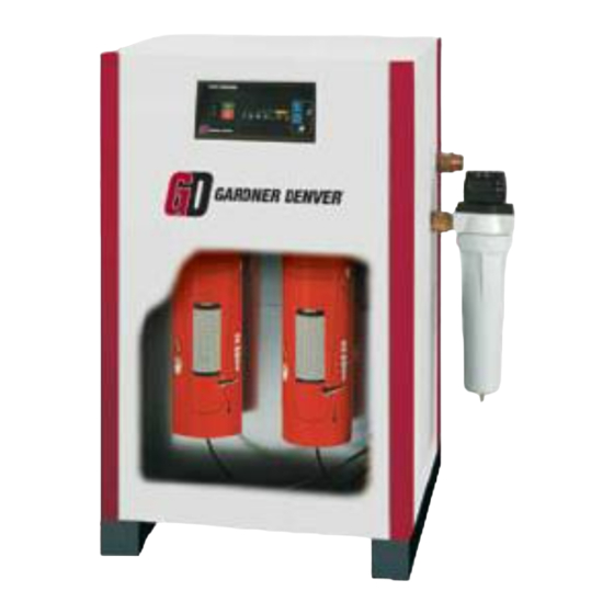
RNC SERIES REFRIGERATED DRYERS
MODELS: RNC25, RNC35, RNC50, RNC75, RNC100
CONTENTS
GENERAL SAFETY INFORMATION ............................ 2
RECEIVING, MOVING, UNPACKING .......................... 2
1.0 INSTALLATION ................................................... 3
2.0 OPERATION ....................................................... 4
3.0 MAINTENANCE ................................................. 6
SIZING ...................................................................... 6
ENGINEERING DATA ................................................. 7
ELECTRICAL SCHEMATICS ........................................ 8
DIMENSIONS / WEIGHTS .......................................... 9
TROUBLESHOOTING ...............................................10
PARTS LIST .............................................................11
WARRANTY ............................................................12
SERVICE DEPARTMENT: (724) 746-1100
1
Advertisement
Table of Contents

Summary of Contents for Gardner Denver RNC25
-
Page 1: Table Of Contents
7610.478.39 6/02 INSTRUCTION MANUAL 18-2-665 RNC SERIES REFRIGERATED DRYERS MODELS: RNC25, RNC35, RNC50, RNC75, RNC100 CONTENTS GENERAL SAFETY INFORMATION ......2 RECEIVING, MOVING, UNPACKING ......2 1.0 INSTALLATION ........... 3 2.0 OPERATION ............4 3.0 MAINTENANCE ..........6 SIZING ..............6 ENGINEERING DATA .......... -
Page 2: General Safety Information
RECEIVING, MOVING, AND UNPACKING GENERAL SAFETY INFORMATION A. RECEIVING PRESSURIZED DEVICES: This shipment has been thoroughly checked, packed This equipment is a pressure and inspected before leaving our plant. It was re- containing device. ceived in good condition by the carrier and was so acknowledged. -
Page 3: Installation
A. Air Inlet - Connect compressed air line from air and service access source to air inlet. (See callout drawing on page 3 for Models RNC25 to RNC100: air in/outlet connection locations) Front 24 inches (610 mm) Back 24 inches (610 mm) -
Page 4: Operation
1.4 Electrical connections 2.0 Operation A. Dryer is designed to operate on the voltage, phase, 2.1 Minimum/Maximum operating conditions and frequency listed on the serial number tag. A. Maximum inlet air pressure: refer to dryer serial B. If dryer is supplied with a cord and plug, install in a number tag receptacle of proper voltage. - Page 5 Inlet Pressure (LED Illuminated indicates Drain Interval 100* drain cycle time) Program RNC25 RNC35 RNC50 RNC75 Press the “Drain Interval Program” button (the “Condensate Draining” LED will start to flash, and RNC100 the illuminated LED on the “Dew Point Temperature * Recommended and pre-programmed factory settings for each RNC Series model dryer.
-
Page 6: Maintenance
3.0 Maintenance Sizing Determining dryer capacity at actual operating 3.1 Condenser coil— Clean off accumulated dust and dirt monthly or as conditions necessary in dirty environments. To determine the maximum inlet flow capacity of a dryer 3.2 Moisture separator/Filter and optional Oil at various operating conditions, multiply the rated Removal Filter—... -
Page 7: Engineering Data
ENGINEERING DATA Minimum – Maximum Operating Conditions RNC25 RNC35 RNC50 RNC75 RNC100 Min.-Max. Inlet Air Pressure (compressed air at inlet to dryer) 30 psig (2.1 kgf/cm ) - 232 psig (16.3 kgf/cm Max. Inlet Air Temp. (compressed air at inlet to dryer) 110°F... -
Page 8: Electrical Schematics
Electrical Schematic Models 25, 35, 50, 75 - 115V/60 Hz Model 50 - 208-230V/60Hz Model 75 - 208-230V/60 Hz; 220-240V/50 Hz Models 100 - All Voltages Legend Optional Notes: SW - On/Off Switch OL - Overload 1. IC1-Includes IC1 Instrument Panel and TB - Terminal Block CAP - Start Capacitor Pneumatic Pilot operated Drains. -
Page 9: Dimensions/Weights
21-13/16 Inlet/Outlet Connections 1/2 MPT 1/2 MPT 1/2 MPT 3/4 MPT 3/4 MPT Weights lbs Weights lbs w/Oil Removal Filter RNC25 thru 50 TOP VIEW FRONT VIEW LEFT SIDE VIEW RNC75 thru 100 TOP VIEW FRONT VIEW LEFT SIDE VIEW... -
Page 10: Troubleshooting
TROUBLESHOOTING GUIDE POSSIBLE CAUSE(S) CORRECTIVE ACTION SYMPTOM 1. Residual free moisture remaining Blow out system with dry air A. Water downstream of dryer in downstream pipelines 2. Air by-pass system is open Check valve positions 3. Inlet and Outlet connections are Check for correct connection reversed 4. -
Page 11: Parts List
G6150-333-2 G6150-333-2 G6150-333-2 G6150-333-2 Digital PC Board (IC 1-0) w/ high temp-sensor G5945-576-7 G5945-576-7 G5945-576-7 G5945-576-7 G5945-576-7 G5945-576-7 Maintenance Kits Model RNC25 RNC35 RNC50 RNC75 RNC100 Standard RNCMK2 RNCMK2 RNCMK3 RNCMK4 RNCMK4 With Optional Cold Coaleser RNCMK12 RNCMK12 RNCMK13 RNCMK14... -
Page 12: Warranty
RETURNED TO THE FACTORY OR IN-WARRANTY REPAIRS ARE MADE. SERVICE DEPARTMENT: (724) 746-1100 For additional information contact your local representative or Gardner Denver Compressor and Pump Division, 1800 Gardner Expressway, Quincy, Illinois 62301 Customer Service Department Telephone: (800) 682-9868 FAX: (217) 228-8243 Sales and Service in all major cities.


Need help?
Do you have a question about the RNC25 and is the answer not in the manual?
Questions and answers