Gardner Denver RNC100 Instruction Manual
Refrigerated type compressed air dryers
Hide thumbs
Also See for RNC100:
- Instruction manual (24 pages) ,
- Instruction manual (12 pages) ,
- Instruction manual (52 pages)
Table of Contents
Advertisement
5002737
Rev. E
07/14
18-2-670
RNC100-750 New Platform
INSTRUCTION MANUAL
RNC Series
Models: RNC100, RNC125, RNC150, RNC200,
RNC250, RNC300, RNC400, RNC500,
RNC600, RNC750
CONTENTS
GENERAL SAFETY INFORMATION .................................. 2
RECEIVING, MOVING, AND UNPACKING ........................ 2
1.0 INSTALLATION ......................................................... 3
2.0 OPERATION ............................................................ 5
3.0 MAINTENANCE ...................................................... 10
SIZING ............................................................................ 12
Models 100-250 ........................................................ 13
Models 300-750 ........................................................ 14
DIMENSIONS / WEIGHTS ................................................ 15
Model 100 (120/230 VAC) ......................................... 16
WIRING DIAGRAM: I-Controller Level 2
100 or 240V/50 Hz) .................................................. 17
Model 750 (230-400-460V/3/50-60 Hz) ................... 20, 21
Models 200-600, (460 VAC) ...................................... 22, 23
Model 750, (460 VAC) ............................................... 24, 25
I-Controller Level 4 (Models 200-750) ...................... 28
Cabinets (all models) ................................................ 29
Models RNC100 through RNC150 ........................... 30, 31
Air-Cooled Units .................................................... 32, 33
Water-Cooled Units............................................... 34, 35
WARRANTY ................................................................... 36
1st Edition
For Sales and Service: (800) 883-2477
Or visit Sales and Service at www.gardnerdenverproducts.com
33F......................39F
1C.......................4C
REFRIGERATED
TYPE
COMPRESSED
AIR DRYERS
Advertisement
Table of Contents

Subscribe to Our Youtube Channel
Related Manuals for Gardner Denver RNC100


Summary of Contents for Gardner Denver RNC100
-
Page 1: Table Of Contents
I-Controller Level 1 & I-Controller Level 2 ....27 I-Controller Level 4 (Models 200-750) ...... 28 REPLACEMENT PARTS: Cabinets (all models) ..........29 Models RNC100 through RNC150 ......30, 31 Models RNC200 through RNC750 Air-Cooled Units ............ 32, 33 Water-Cooled Units..........34, 35 WARRANTY .............. -
Page 2: General Safety Information
GENERAL SAFETY INFORMATION RECEIVING, MOVING, AND UNPACKING PRESSURIZED DEVICES: RECEIVING This equipment is a pressure containing This shipment has been thoroughly checked, packed and device. inspected before leaving our plant. It was received in good condition by the carrier and was so acknowledged. •... -
Page 3: Installation
Clearances: Minimum requirements for free air flow and service access Front 36 inches (914 mm) Model Back 6 inches (152 mm) RNC100 Sides 36 inches (914 mm) Standard units are designed to operate in ambients: Control Panel Air-cooled: 40 to 110°F (4 to 43°C). -
Page 4: Wiring Diagram: I-Controller Level
1.3 Piping connections 1.5 Moisture separator Model 100: Air Inlet - Connect compressed air line from air source to Separator (and Oil Removal Filter where air inlet. (Reference markings on dryer for air inlet/outlet applicable) has an internal drain which connection locations) automatically discharges collected condensate. -
Page 5: Operation
2.0 OPERATION 2.1 Minimum/Maximum operating conditions Maximum inlet air pressure: refer to dryer serial number Minimum inlet air pressure: 30 psig (2.1 kgf/cm Maximum inlet air temperature: 120°F (49°C) Maximum ambient temperature: Air-cooled models: 110°F (43°C) Water-cooled models: 130°F (54°C) Minimum ambient temperature: 40°F (4°C) Models 200-750 MRD200-750... - Page 6 Inlet Pressure 100* NOTE: In the event of a brief or extended period of power RNC100 loss, the unit will retain the existing program setting and will RNC125 begin a new cycle once power is reapplied. Had drain been RNC150 ready to drain before the loss of power, the drain bowl’s...
- Page 7 Language selection I - CONTROLLER LEVEL 4 a. Use the ‘Up’ and ‘Down’ arrow buttons to scroll through the list of languages (choice of 10 available: English, Deutsch, Francais, Espanol, Italiano, Polski, Dansk, Dutch, Norsk and Suomi). b. Press ‘Enter’ button to select the language that is displayed.
- Page 8 Push ESC button to exit program mode Operating check points NOTE: If after 60 seconds no button is pressed while in Check that green Power-on light is illuminated Program Mode, the audible alarm sounds for five (5) Check that green Compressor-on light is illuminated if seconds.
- Page 9 f. Check drain operation - push Drain (push-to-test) button to energize electric drain. A flow of condensate and/or air should be present at the drain outlet. Using the RS-232 port The RS-232 port is used to monitor dryer operation from a host computer.
-
Page 10: Maintenance
Depressurize filter by slowly opening manual drain by- pass valve. Remove bowl Models RNC125 thru RNC150 For models RNC100 through RNC150 - bayonet mount - push bowl up, turn bowl 1/8th turn to your left, and pull bowl straight down For models RNC200 through RNC750 - threaded bowls - unscrew bowl from head using hand, strap wrench or C spanner. - Page 11 3.3 Check separator daily to be sure automatic drain is discharging. NOTE: Units with two stage filtration have two sets of drains. 3.4 Blow down separator weekly by pushing test button on control panel. 3.5 Rebuild drain mechanism annually. To facilitate service, maintenance kits are available. See page 26.
-
Page 12: Sizing
SIZING TABLE 2 Air capacity correction factors (Multipliers) Determining dryer capacity at actual operating conditions INLET COMPRESSED AIR CONDITIONS To determine the maximum inlet flow capacity of a dryer INLET TEMPERATURES INLET at various operating conditions, multiply the rated capacity PRESSURES from Table 1 by the multipliers shown in Table 2. -
Page 13: Engineering Data: Models 100-250
ENGINEERING DATA: MODELS 100-250 Air System Data Rated Flow Capacity at 100°F, 100 psig Inlet, 100°F Ambient Temperature Maximum / Minimum Inlet Air Pressure (compressed air at inlet to dryer) 232 psig (16 barg) / 30 psig (2.1 barg) Maximum / Minimum Inlet Air Temperature (compressed air at inlet to dryer) 120°F (49°C) / 40°F (4°C) Maximum / Minimum Ambient Temperature Air-cooled: 110°F (43°C) / 40°F (4°C), Water-cooled: 130°F (54°C) / 40°F (4°C) -
Page 14: Models 300-750
ENGINEERING DATA: MODELS 300-750 Air System Data Rated Flow Capacity at 100°F, 100 psig Inlet, 100°F Ambient Temperature Maximum / Minimum Inlet Air Pressure (compressed air at inlet to dryer) 232 psig (16 barg) / 30 psig (2 barg) Maximum / Minimum Inlet Air Temperature (compressed air at inlet to dryer) 120°F (49°C) / 40°F (4°C) Maximum / Minimum Ambient Temperature Air-cooled: 110°F (43°C) / 40°F (4°C), Water-cooled: 130°F (54°C) / 40°F (4°C) -
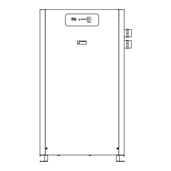
Page 15: Dimensions / Weights
DIMENSIONS / WEIGHTS Dimensions, inches (mm) Model 37.56 (954) 37.56 (954) 37.56 (954) 38.60 (980) 38.60 (980) 45.38 (1153) 45.38 (1153) 58.06 (1475) 58.06 (1475) 58.06 (1475) 25.62 (651) 25.62 (651) 25.62 (651) 32.15 (817) 32.15 (817) 32.15 (817) 32.15 (817) 32.15 (817) 32.15 (817) 32.15 (817) -
Page 16: Model 100 (120/230 Vac)
WIRING DIAGRAM I-Controller Level 1 Model 100 (120/230 VAC) -
Page 17: Model 100 Thru 150 (115 Or 208-230V/60 Hz, 100 Or 240V/50 Hz)
WIRING DIAGRAM I-Controller Level 2 Model 100 thru 150 (115 or 208-230V/60 Hz, 100 or 240V/50 Hz) -
Page 18: Models 200 Thru 600 (230-400-460V/3/50-60 Hz)
WIRING DIAGRAM I-Controller Level 2 Models 200 thru 600 (230-400-460V/3/50-60 Hz) Sheet 1 of 2... - Page 19 WIRING DIAGRAM I-Controller Level 2 Models 200 thru 600 (230-400-460V/3/50-60 Hz) Sheet 2 of 2...
-
Page 20: Model 750 (230-400-460V/3/50-60 Hz)
WIRING DIAGRAM I-Controller Level 2 Model 750 (230-400-460V/3/50-60 Hz) Sheet 1 of 2... - Page 21 WIRING DIAGRAM I-Controller Level 2 Model 750 (230-400-460V/3/50-60 Hz) Sheet 2 of 2...
-
Page 22: Models 200-600, (460 Vac)
WIRING DIAGRAM I-Controller Level 4 Models 200-600, (460 VAC) Sheet 1 of 2... - Page 23 WIRING DIAGRAM I-Controller Level 4 Models 200-600, (460 VAC) Sheet 2 of 2...
-
Page 24: Model 750, (460 Vac)
WIRING DIAGRAM I-Controller Level 4 Model 750, (460 VAC) Sheet 1 of 2... - Page 25 WIRING DIAGRAM I-Controller Level 4 Model 750, (460 VAC) Sheet 2 of 2...
-
Page 26: Models 200-750, 575-460/3/60 Transformer Pack
WIRING DIAGRAM Models 200-750, 575-460/3/60 Transformer Pack... -
Page 27: Troubleshooting Guide: I-Controller Level 1 & I-Controller Level 2
TROUBLESHOOTING GUIDE: I-CONTROLLER LEVEL 1 & I-CONTROLLER LEVEL 2 SYMPTOM POSSIBLE CAUSE(S) CORRECTIVE ACTION A) Water downstream of dryer. 1. Residual free moisture remaining in Blow out system with dry air. downstream pipelines. 2. Air bypass system is open. Check valve positions. 3. -
Page 28: I-Controller Level 4 (Models 200-750)
TROUBLESHOOTING GUIDE: I-CONTROLLER LEVEL 4 (MODELS 200-750) SYMPTOM POSSIBLE CAUSE(S) CORRECTIVE ACTION A) Water downstream of dryer 1. Residual free moisture remaining in 1. Blow out system with dry air downstream pipelines 2. Air bypass system is open 2. Check valve positions 3. -
Page 29: Replacement Parts: Cabinets (All Models)
REPLACEMENT PARTS: Cabinets (all models) REPLACEMENT CABINET PARTS- Models RNC100 through RNC150 ID # PARTS DESCRIPTION Cabinet Panel - Top G5002267 G5002267 G5002267 Cabinet Panel - Front G5002121 G5002121 G5002121 Cabinet Panel - Rear G5002272 G5002272 G5002272 Cabinet Panel - Left... - Page 30 REPLACEMENT PARTS: Models RNC100 through RNC150 VIEW ORIENTATION REFERENCE RIGHT REAR, VIEW-A (covers and center support shelf removed for clarity) RIGHT FRONT, VIEW-B (covers and center support shelf removed for clarity) 13 14 LEFT REAR, VIEW-C (covers and center support shelf removed for clarity)
- Page 31 REPLACEMENT PARTS: Models RNC100 through RNC150 MAINTENANCE KITS MODEL Kit Components Standard Kit Separator Element, O-Ring, Drain Service Kit, Lube Packet, Service Reminder RNCMK22S RNCMK23S RNCMK23S Decal Separator Element, Cold Coalescing Element, O-Ring, Drain Service Kit, Lube Cold Coalescing Kit...
-
Page 32: Models Rnc200 Through Rnc750 Air-Cooled Units
REPLACEMENT PARTS: Models RNC200 through RNC750 (Air-Cooled Units) VIEW ORIENTATION REFERENCE RIGHT REAR, VIEW-A (covers and center support shelf removed for clarity) 33F......39F 1C.......4C IC2 Control Panel RIGHT FRONT, VIEW-B (covers and center support shelf removed for clarity) 11 12 LEFT REAR, VIEW-C (covers and center support shelf removed for clarity) - Page 33 ** Items 13, 14, 15, 16, 17, 18, 19, 20, 21, 22, and 26 are located in the electrical enclosure located behind the control panel. Refer to the appropriate Electrical Schematic to identify part. Gardner Denver Inc. Phone: (800) 682-9868...
-
Page 34: Water-Cooled Units
REPLACEMENT PARTS: Models RNC200 through RNC750 (Water-Cooled Units) VIEW ORIENTATION REFERENCE RIGHT REAR, VIEW-A (covers and center support shelf removed for clarity) 19 20 33F......39F 1C.......4C IC2 Control Panel RIGHT FRONT, VIEW-B (covers and center support shelf removed for clarity) LEFT REAR, VIEW-C (covers and center support shelf removed for clarity) - Page 35 ** Items 8, 9, 10, 11, 12, 13, 14, 15, 16, 17, and 21 are located in the electrical enclosure located behind the control panel. Refer to the appropriate Electrical Schematic to identify part. Gardner Denver Inc. Phone: (800) 682-9868...
-
Page 36: Warranty
Gardner Denver Inc. 1800 Gardner Expressway, Quincy, IL 62305 Telephone: (800) 682-9868 FAX: (217) 224-7814 Visit our Web Site: www.gardnerdenverproducts.com © 2014 Gardner Denver, Inc. Printed in U.S.A 5002737 Rev. E 07/14 18-2-670 RNC100-750 New Platform 1st Edition...
Need help?
Do you have a question about the RNC100 and is the answer not in the manual?
Questions and answers