
Subscribe to Our Youtube Channel
Related Manuals for Burkert 2933


Summary of Contents for Burkert 2933
- Page 1 Type 2933, 2934, 2935, 2973, 2974, 2975 Manually operated diaphragm valves Operating Instructions Bedienungsanleitung Manuel d‘utilisation...
- Page 2 We reserve the right to make technical changes without notice. Technische Änderungen vorbehalten. Sous réserve de modifications techniques. © Bürkert Werke GmbH & Co. KG, 2023 Operating Instructions 2304/00_EU-ML_00815442 / Original DE...
-
Page 3: Table Of Contents
Type 2933, 2934, 2935, 2973, 2974, 2975 Table of contents Set stroke limit ............20 OPERATING INSTRUCTIONS ..........4 Lock handwheel ............21 Symbols ............... 4 1.2 Definition of terms ............4 MAINTENANCE ..............22 INTENDED USE ..............5 Cleaning ..............22 Maintenance work ............. -
Page 4: Operating Instructions
Definition of terms DANGER Term Definition for these instructions Warning of an immediate danger. Device Diaphragm valve type 2933, 2934, 2935, ▶ Failure to comply will result in death or serious injury. 2973, 2974 and 2975 Ex area Potentially explosive atmosphere... -
Page 5: Intended Use
INTENDED USE BASIC SAFETY INSTRUCTIONS These safety instructions do not take into account any unforeseen The diaphragm valve type 2933, 2934, 2935, 2973, 2974 and circumstances or events that occur during installation, operation 2975 is designed to control the flow of media. The authorised and maintenance. The operator is responsible for observing media are listed in chapter “Technical data”. - Page 6 Type 2933, 2934, 2935, 2973, 2974, 2975 Basic safety instructions ▶ The process must be restarted in a defined or controlled manner Medium may leak out if the diaphragm is worn. after an interruption in the power supply or pneumatic supply. ▶ Inspect relief bore for any medium leakages. ▶ Change the diaphragm if medium leaks. ▶ The device may be operated only when in perfect condition and in consideration of the operating instructions. ▶ If the medium is hazardous, secure the area around the leakage to prevent risks. ▶ For applications planning and operation of the device, observe the plant-specific safety regulations. Danger of crushing due to mechanically moving parts.
-
Page 7: General Notes
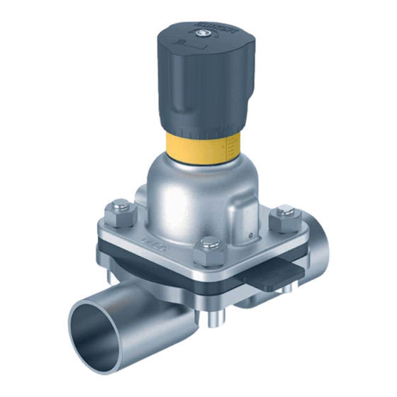
International The contact addresses can be found on the back pages of the printed operating instructions. Handwheel They are also available online at: country.burkert.com Attachment with scale Warranty A precondition for the warranty is that the diaphragm valve is used as intended in consideration of the specified operating conditions. Diaphragm Information on the Internet Valve body Operating instructions and data sheets for type 2933, 2934, 2935, 2973, 2974, 2975 can be found online at: Port connection country.burkert.com Fig. 1: Example of 2/2-way valve, type 2933 english... -
Page 8: Function
Type 2933, 2934, 2935, 2973, 2974, 2975 Product description 5.2.2 Type 2934 with T-valve body 5.2.4 Type 2973, 2974, 2975 Handwheel with lock Handwheel (optional) Attachment with scale Attachment with scale Diaphragm Diaphragm T-Valve body Valve body Port connection Port connection Fig. -
Page 9: Product Identification
Type 2933, 2934, 2935, 2973, 2974, 2975 Product description The scale on the handwheel determines the rotation position of The visibility of the yellow marking is not directly related the handwheel (type 293x: 30 positions, type 297x: 50 positions). to the closed position of the valve. Depending on the con- struction of the valve, the marking may: The reproducible stroke scale shows the relative position of the - not be visible when the valve is open, or valve and serves as a fixed point for determining the rotational - visible when the valve is closed. - Page 10 Type 2933, 2934, 2935, 2973, 2974, 2975 Product description 5.4.2 Labelling on forged steel valve body 5.4.3 Labelling on cast valve body XX F XXXXXXXX/XXX 1.4435/316L(VS) XXXX PN16/CWP150 XXXXXX XXXXXXXXXX Fig. 7: Labelling on forged steel valve body Item Description...
-
Page 11: Technical Data
Type 2933, 2934, 2935, 2973, 2974, 2975 Technical data TECHNICAL DATA 5.4.4 Labelling on tube valve body Standards and directives The device complies with the valid EU harmonisation legislation. 1.4435 316L(VP) In addition, the device also complies with the requirements of the XXXXXXXX laws of the United Kingdom. The harmonised standards that have been applied for the conformity PN16 / CWP150 assessment procedure are listed in the current version of the EU Declaration of Conformity/ UK Declaration of Conformity. -
Page 12: Port Connections Valve Body
Type 2933, 2934, 2935, 2973, 2974, 2975 Technical data Port connections valve body Medium temperature for diaphragms EPDM (AD) -10...+143 °C Stainless steel valve body Welded connection Steam sterilisation up to +150 °C for Clamp connection 60 min Plastic valve body Spigot FKM (FF) 0...+130 °C True union No steam/dry heat up to +150 °C for Operating conditions 60 min... - Page 13 Type 2933, 2934, 2935, 2973, 2974, 2975 Technical data 6.4.2 Permitted medium pressure Maximum permitted medium pressure The values are valid for valve bodies made from: Permitted medium pressure for plastic valve bodies depending on • Plastic, medium temperature: • Stainless steel: block material, forged or casted and tube valve body. Nominal Maximum permitted medium pressure diameter [bar] EPDM/FKM PTFE/advanced (diaphragm PTFE/Gylon® size) PVDF PVC-U Temperature [°C]...
-
Page 14: Flow Values
Type 2933, 2934, 2935, 2973, 2974, 2975 Technical data Flow values 20 / 3/4" EPDM 12.4 12.5 PTFE 12.0 12.0 6.5.1 Flow values for forged steel valve 25 / 1" EPDM 20.0 18.0 15.5 16.0 bodies PTFE 17.0 16.0 14.5 14.8... - Page 15 Type 2933, 2934, 2935, 2973, 2974, 2975 Technical data 6.5.2 Flow values for cast valve bodies 6.5.3 Flow values for tube valve bodies Kv values [m /h] for cast valve bodies VG Kv values [m /h] for tube valve body VP (IHU2) TVB3G...
-
Page 16: Installation
Type 2933, 2934, 2935, 2973, 2974, 2975 Installation INSTALLATION 25 / 1" EPDM 17.3 PTFE 14.1 DANGER EPDM 18.6 Risk of injury due to high pressure and escaping medium. PTFE 14.2 ▶ Switch off the pressure before working on the device or system. 25 / 1" EPDM 19.1 Vent or empty the lines. -
Page 17: Information For The Correct Installation Position
Type 2933, 2934, 2935, 2973, 2974, 2975 Installation Information for the correct • The marking on the port connection of valve bodies serves as an orientation aid. The marking must point upwards. installation position • The actual self-draining angle must be set with a suitable Depending on the valve body, the installation position of the dia- measuring tool. phragm valve is different. • For valve bodies without angle information, you can find the Installation for leakage detection: self-draining angle on the Internet: www.burkert.com One of the relief bores in the diaphragm socket for moni- Type /Manuals /Supplementary information toring leakages must be at the lowest position. -
Page 18: Preparatory Work
Type 2933, 2934, 2935, 2973, 2974, 2975 Installation Preparatory work 7.1.2 Installation position of T-valve body The following installation positions are recommended for the instal- → Clear impurities from pipelines (seal material, metal chips, etc.). lation of the T-valve in circular pipelines: → Support and align pipelines. When medium is fed: When medium is removed: Devices with bonded or adhesive bodies: The actuator and diaphragm must be dismantled before welding or bonding the valve body. -
Page 19: Install Device
Type 2933, 2934, 2935, 2973, 2974, 2975 Installation Install device For information on containers and instructions for welding, refer to the ASME VIII Division I standard. Check the batch NOTE number indicated on the manufacturer’s certificate 3.1 The following must be heeded when installing the device in supplied before starting welding work. the system: ▶ The device and relief bore must be accessible for inspections Observe the applicable laws of the country with regard to and maintenance work. the qualification of welders and the execution of welding 7.3.1... -
Page 20: Set Stroke Limit
Type 2933, 2934, 2935, 2973, 2974, 2975 Installation Set stroke limit NOTE Damage to the device when failing to observe tightening torque. 7.4.1 Set stroke limit, type 293x ▶ Observe tightening torques. Minimum stroke limit is available for type 2933, 2934 and 2935. → Tighten each fastening screw in 3 stages (approx. 1/3, approx. A hexagon nut is used for this purpose. 2/3, 3/3 of the tightening torque in accordance with “Tab. 5”) → Turn the handwheel clockwise to move the valve to the closed crosswise. -
Page 21: Lock Handwheel
Type 2933, 2934, 2935, 2973, 2974, 2975 Installation NOTE Screw on handwheel Damage to the device due to incorrectly positioned hexagon Square nut. Adjusting sleeve ▶ Do not screw the hexagon nut in the area of the square. ▶ Use min. stroke limitation only in the range of 0-25 % opening stroke. → Tighten the screw on the handwheel with 0.9 Nm. -
Page 22: Maintenance
Type 2933, 2934, 2935, 2973, 2974, 2975 Maintenance MAINTENANCE DANGER Risk of injury due to high pressure and escaping medium. ▶ Switch off the pressure before working on the device or system. Vent or empty the lines. Risk of escaping medium if the diaphragm is worn. Locking pin ▶ Check the relief bore for escaping medium. -
Page 23: Maintenance Work
Type 2933, 2934, 2935, 2973, 2974, 2975 Maintenance Maintenance work • Medium pressure • Medium temperature 8.2.1 Actuator • Closing force When used in accordance with these operating instructions, the → If there is a leak, replace the wearing part in question with a actuator is maintenance-free. - Page 24 Type 2933, 2934, 2935, 2973, 2974, 2975 Maintenance NOTE Handwheel Damage to the diaphragm with threaded connection due to live pin. ▶ First screw on the diaphragm hand-tight, then loosen it by rotating it anticlockwise with one half-turn. → Install new diaphragm in the actuator (see “Tab. 6”). → Rotate the handwheel anticlockwise until it comes to a stop Fastening (UP position).
-
Page 25: Replacement Parts, Accessories
Type 2933, 2934, 2935, 2973, 2974, 2975 Replacement parts, accessories REPLACEMENT PARTS, 8.3.1 Change between PTFE and EPDM diaphragms ACCESSORIES DN8: CAUTION → Unbutton PTFE diaphragm and button on new EPDM diaphragm. Risk of injury and/or damage due to incorrect parts. -
Page 26: Replacement Diaphragms
Type 2933, 2934, 2935, 2973, 2974, 2975 Replacement parts, accessories Replacement diaphragms Replacement diaphragms can be ordered according to the table below. The diaphragms are marked with a material code that specifies them. The material code is located on the identification tab or, in the case of two-piece diaphragms, on the tab of the support diaphragm and the diaphragm plate (see “Fig. 16”). The material code may differ for older materials. Diaphragm fixings see “Tab. 6”. Advanced PTFE / EPDM Gylon® laminated / EPDM Diaphragm EPDM PTFE / EPDM (EU*) (ER*) size (AD*) (FF*) (EA*) Article Material Article Material Article Material... -
Page 27: Transportation, Storage, Disposal
Type 2933, 2934, 2935, 2973, 2974, 2975 Transportation, storage, disposal TRANSPORTATION, STORAGE, DISPOSAL CAUTION Risk of injury due to heavy device. During transportation or installation work, a heavy device may fall down and cause injuries. ▶ Heavy equipment must only be transported, assembled and disassembled with the help of a second person. ▶ Use suitable tools. - Page 29 www.burkert.com...
Need help?
Do you have a question about the 2933 and is the answer not in the manual?
Questions and answers