Peak PCAN-miniPCIe Single Channel User Manual
Can interface for pci express mini
Hide thumbs
Also See for PCAN-miniPCIe Single Channel:
- User manual (26 pages) ,
- User manual (30 pages)

Related Manuals for Peak PCAN-miniPCIe Single Channel


Summary of Contents for Peak PCAN-miniPCIe Single Channel
- Page 1 PCAN-miniPCIe CAN Interface for PCI Express Mini User Manual Document version 1.2.1 (2014-04-30)
- Page 2 All other product names mentioned in this document may be the trademarks or registered trademarks of their respective companies. They are not explicitly marked by “™” or “®”. © 2014 PEAK-System Technik GmbH PEAK-System Technik GmbH Otto-Roehm-Strasse 69 64293 Darmstadt...
-
Page 3: Table Of Contents
PCAN-miniPCIe – User Manual Contents Introduction Properties at a Glance System Requirements Scope of Supply Installing the Software and the Card Connecting the CAN Bus D-Sub Connector Cabling 3.2.1 Termination 3.2.2 Example of a Connection 3.2.3 Maximum Bus Length Using the Software CAN Monitor PCAN-View for Windows 4.1.1 Receive/Transmit Tab... -
Page 4: Introduction
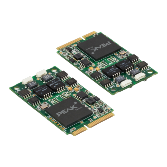
PCAN-miniPCIe – User Manual Introduction The PCAN-miniPCIe card enables the connection of embedded PCs and laptops with PCI Express Mini slots to CAN networks. There is galvanic isolation of up to 300 Volts between the computer and CAN sides. Device drivers and a programming interface exist for different operating systems, so programs can easily access a connected CAN bus. -
Page 5: System Requirements
Windows. You can find device drivers for Linux and the corresponding application information on the provided DVD in the Develop directory branch and on our website under www.peak-system.com/linux. System Requirements A vacant PCI Express Mini slot in the computer... -
Page 6: Installing The Software And The Card
PCAN-miniPCIe – User Manual Installing the Software and the Card This chapter covers the software setup for the PCAN-miniPCIe card under Windows and the installation in the computer. Setup the driver before installing the PCAN-miniPCIe card for the first time. Do the following to install the driver and additional software: Make sure that you are logged in as user with administrator privileges (not needed for normal use of the card later on). - Page 7 PCAN-miniPCIe – User Manual Disconnect the computer from the power supply. Open the computer's casing. Insert the PCAN-miniPCIe card into an empty PCI Express Mini slot. For details refer to the documentation of the computer. For each CAN channel, mount a D-Sub connector with connection circuit board into a respective hole of the computer casing.
- Page 8 PCAN-miniPCIe – User Manual Do the following to complete the initialization: Turn on the computer and start Windows. Make sure that you are logged in as user with administrator privileges. Windows notifies that new hardware has been detected. The drivers are found and installed by Windows. Afterwards you can work as user with restricted rights again.
-
Page 9: Connecting The Can Bus
PCAN-miniPCIe – User Manual Connecting the CAN Bus D-Sub Connector A High-speed CAN bus (ISO 11898-2) is connected to a 9-pin D-Sub connector. The pin assignment for CAN corresponds to the specification CiA® 102. Figure 2: Pin assignment High-speed CAN (view onto a D-Sub connector) Figure 3: PCAN-miniPCIe card with connection cables... - Page 10 PCAN-miniPCIe – User Manual To connect a CAN bus to the PCAN-miniPCIe card, use the supplied special connection cables. After you've plugged in the cable on the PCAN-miniPCIe card, you can connect a CAN bus to the D-sub socket. The pin assignment between the D-Sub port and the 4-pin connector on the PCAN-miniPCIe card is as follows: Figure 4: Front view of a CAN connector (SUR)
-
Page 11: Cabling
PCAN-miniPCIe – User Manual Cabling 3.2.1 Termination A High-speed CAN bus (ISO 11898-2) must be terminated on both ends with 120 Ohms. Otherwise, there are interfering signal reflec- tions and the transceivers of the connected CAN nodes (CAN interface, control unit) do not work. The PCAN-miniPCIe card does not have an internal termination. -
Page 12: Maximum Bus Length
PCAN-miniPCIe – User Manual 3.2.3 Maximum Bus Length High-speed CAN networks may have bit rates of up to 1 Mbit/s. The maximum bus length is primarily depending on the bit rate. The following table shows the maximum CAN bus length at different bit rates: Bit rate Bus length... -
Page 13: Using The Software
PCAN-miniPCIe – User Manual Using the Software This chapter covers the provided software PCAN-View and the programming interface PCAN-Basic. CAN Monitor PCAN-View for Windows PCAN-View for Windows is a simple CAN monitor for viewing, transmitting, and logging CAN messages. Figure 6: PCAN-View for Windows Do the following to start and initialize PCAN-View: If PCAN-View is already installed on the hard disk, open the Windows Start menu, go to Programs >... - Page 14 PCAN-miniPCIe – User Manual If you haven't installed PCAN-View together with the device driver, you can start the program directly from the supplied DVD. In the DVD navigation program (Intro.exe), go to English > Tools, and under PCAN-View for Windows select the Start link.
-
Page 15: Receive/Transmit Tab
PCAN-miniPCIe – User Manual 4.1.1 Receive/Transmit Tab Figure 8: Receive/Transmit tab The Receive/Transmit tab is the main element of PCAN-View. It contains two lists, one for received messages and one for the transmit messages. Representation of CAN data is in hexadecimal format. - Page 16 PCAN-miniPCIe – User Manual Figure 9: Dialog box New transmit message Enter the ID and the data for the new CAN message. The Cycle Time field indicates if the message will be trans- mitted manually or periodically. If you want to transmit the message periodically, you must enter a value greater than 0.
-
Page 17: Trace Tab
PCAN-miniPCIe – User Manual 4.1.2 Trace Tab Figure 10: Trace tab On the Trace tab the data tracer of PCAN-View is used for logging the communication on a CAN bus. During this process the CAN messages are cached in the working memory of the PC. Afterwards they can be saved to a file. -
Page 18: Status Bar
PCAN-miniPCIe – User Manual 4.1.3 Status Bar Figure 11: Example of the status bar The status bar shows information about the current CAN connec- tion, about error counters (Overruns, QXmtFull), and error messages. You can find further information about the use of PCAN-View in the help which you can invoke in the program via the Help menu or with the F1 key. -
Page 19: Linking Own Programs With Pcan-Basic
On the provided DVD you can find files of the programming inter- face PCAN-Basic in the Develop directory branch. This API provides basic functions for linking own programs to CAN interfaces by PEAK-System and can be used for the following operating systems: Windows 8, 7, Vista (32/64-bit) Windows CE 6.x (x86/ARMv4) Linux (32/64-bit) The API is designed for cross-platform use. -
Page 20: Features Of Pcan-Basic
Use of up to 8 channels for each hardware unit (depending on the PEAK CAN interface used) Simple switching between channels of a PEAK CAN interface Driver-internal buffer for 32768 messages per CAN channel Precision of time stamps on received messages up to 1 μs... -
Page 21: Principle Description Of The Api
PCAN-miniPCIe – User Manual 4.2.2 Principle Description of the API The PCAN-Basic API is the interface between the user application and device driver. In Windows operating systems this is a DLL (Dynamic Link Library). The sequence of accessing the CAN interface is divided into three phases: 1. -
Page 22: Notes About The License
Notes about the License Device drivers, the interface DLL, and further files needed for linking are property of the PEAK-System Technik GmbH and may be used only in connection with a hardware component purchased from PEAK-System or one of its partners. If a CAN hardware component... -
Page 23: Technical Specifications
PCAN-miniPCIe – User Manual Technical Specifications Connectors Computer PCI Express Mini slot, 52-pin; electromechanical specifications 1.1 and 1.2 CAN (via cable) D-Sub (m), 9-pin, assignment according to specification CiA® 102 CAN (on card) Connector type SUR from JST (www.jst-mfg.com), name of the matching plug: 04SUR-32S Specification ISO 11898-2, High-speed CAN 2.0A (Standard format) and 2.0B (Extended format) - Page 24 PCAN-miniPCIe – User Manual Environment Operating -40 - 85 °C (-40 - 185 °F) temperature Temperature for -40 - 100 °C (-40 - 212 °F) storage and transport Relative humidity 15 - 90 %, not condensing EN 55024:2011-09 EN 55022:2011-12 EC directive 2004/108/EG...
-
Page 25: Appendix Ace Certificate
PCAN-miniPCIe – User Manual Appendix A CE Certificate... -
Page 26: Appendix B Dimension Drawing
PCAN-miniPCIe – User Manual Appendix B Dimension Drawing Figure 13: View PCAN-miniPCIe The figure does not show the actual size of the product. -
Page 27: Appendix C Quick Reference
PCAN-miniPCIe – User Manual Appendix C Quick Reference Software/Hardware Installation under Windows Before installing the PCAN-miniPCIe card into the computer please set up the corresponding software package from the supplied DVD (with administrator privileges). Afterwards, insert the PCAN- miniPCIe card into a vacant PCI Express Mini slot of the switched off (de-energized) computer.
Need help?
Do you have a question about the PCAN-miniPCIe Single Channel and is the answer not in the manual?
Questions and answers