Table of Contents
Advertisement
Quick Links
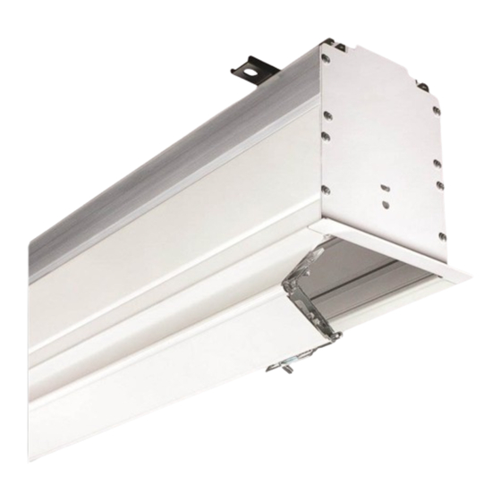
Ultimate Access E and V
Electric projection screen
Overview - Components
Mounting Bracket
Electrical Cutout
Tab Tensioning
"V" Dowel
Shipping Brackets Attached
to Dowel and Screen Case
(V Screens Only)
Please Note: Shipping brackets must remain in place
until product has been mounted and connected to
power
(see Sections 1 and 4 in this document.)
Also, DO NOT operate screen before removing
shipping brackets from screen case.
Read and understand all warnings
Contents
Overview - Components ...............................................................................................1
Section 1 - Removing Shipping Brackets
PLEASE READ - Safety Information ............................................................................2
Section 2 - Hanging Screen .........................................................................................3
Section 3 - Bottom Access Panel/Trap Door Opening and Closing .....................3
Section 4 - Motorized Roller/Fabric Installation ......................................................4
Section 5 - Motorized Roller/Fabric Removal ..........................................................4
Section 6 - Operation ...................................................................................................5
Leveling Bracket
Hoisting Bracket
"V " Fl ex ib le V in yl
V ie w in g S u rf ac e
.
CAUTION
..............2
Hoisting Bracket
"E " Fr ee H an g in g
V ie w in g S u rf ac e
TOOLS REQUIRED
PENCIL
HARDWARE
before beginning installation.
(page 2)
Section 7 - Tab-Tension Adjustment Procedure ......................................................5
Section 8 - Electrical Connections ............................................................................5
Section 9 - Limit Adjustments .....................................................................................5
Section 10 - Case Length Dimensions .......................................................................6
Section 11 - Case Width Dimensions .........................................................................6
Section 12 - Mounting Bracket Dimensions .............................................................6
Section 14 - Wiring Diagrams ......................................................................................7
Ultimate Access screen, call your dealer or Draper, Inc.
© 2022 All Rights Reserved
INSTRUCTIONS
INSTALLATION & OPERATION
Mounting Bracket
Trim Flange
"E" Dowel
POWER DRILL
TAPE MEASURE
LEVEL
(by others)
........................7
If you have any difficulties installing or servicing your
Draper, Inc. | 411 S. Pearl St. Spiceland, IN 47385
draperinc.com | 765.987.7999 | 800.238.7999
|
FORM: UltimateAccess_Inst22
Advertisement
Table of Contents

Subscribe to Our Youtube Channel
Related Manuals for Draper Ultimate Access V


Summary of Contents for Draper Ultimate Access V
-
Page 1: Table Of Contents
Section 14 - Wiring Diagrams ..................7 If you have any difficulties installing or servicing your Ultimate Access screen, call your dealer or Draper, Inc. Draper, Inc. | 411 S. Pearl St. Spiceland, IN 47385 draperinc.com | 765.987.7999 | 800.238.7999 FORM: UltimateAccess_Inst22... -
Page 2: Please Read - Safety Information
9. Do not wire motors in parallel without written permission from Draper, Inc. 2. Installation and calibration of the unit should only be performed by an 10. During testing or operation, carefully watch the surrounding area for any authorized, qualified, and experienced professional. -
Page 3: Section 2 - Hanging Screen
Ultimate Access E and V page 3 of 7 Section 2 - Hanging Screen Please Note: When locating viewing surface and checking clearance HOISTING HOISTING HOISTING HOISTING BRACKET BRACKET BRACKET BRACKET for screen operation, ensure that surface is centered in the case. CASE CASE MOUNTING... -
Page 4: Section 4 - Motorized Roller/Fabric Installation
Ultimate Access E and V page 4 of 7 IDLER END OF CASE MOTOR END OF CASE Figure 5 BOTTOM VIEW BOTTOM VIEW SIDE VIEW SIDE VIEW Set Screws Idler End Motor End Mounting Mounting Bracket Bracket Figure 6 Figure 7 Motor End Idler End Retaining Clip... -
Page 5: Section 6 - Operation
(30 cm) down travel. could void the warranty. down travel. and turn off. Please check with Draper 2. Turn DOWN limit screw clockwise (3 screw turns = 1/2 roller revolution) prior to resetting screen limits. 3. Test by lowering screen. Repeat steps 1 & 2 until desired position is reached. -
Page 6: Section 10 - Case Length Dimensions
ACCESS (67mm) 6 " Ultimate Access E and V (171mm) page 6 of 7 7 " (187mm) 8" (203mm) Motor Wiring is on the Section 10 - Case Length Dimensions AUDIENCE LEFT END of Screen Case. CASE LENGTH " 2" 18"... -
Page 7: Section 13 - Accessing Built-In Low-Voltage Control Unit
Ultimate Access E and V page 7 of 7 Section 13 - Accessing Built-In Low-Voltage Control Unit (LVC-IV) PLEASE NOTE: Applies ONLY if Unit is built into case. MOTOR END OF CASE (Bottom View) 1.. Locate junction box on motor end of screen. (Fig.
Need help?
Do you have a question about the Ultimate Access V and is the answer not in the manual?
Questions and answers