Table of Contents
Advertisement
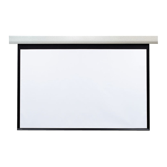
Acumen
XL E & V
™
Electric projection screen
Overview - Components
Electrical Knock-outs
(Top and Back)
Motor Wiring
Access Panel
Read and understand all warnings
Contents
Overview - Components .......................................................................................1
PLEASE READ - Safety Information ....................................................................2
Section 1 - Electrical Connections .....................................................................2
Section 2 - Fascia Removal .................................................................................3
Section 4 - Operation............................................................................................3
Section 5 - Hanging Screen .................................................................................4
Removable Fascia
CAUTION
(Page 2 of this document)
..............3
Wall / Ceiling
Mounting Brackets
before beginning installation.
Section 6 - Limit Adjustments .............................................................................6
Section 7 - Wiring: Standard and Quiet Motor .................................................7
Section 10 - Tab-Tension Adjustment Procedure ..........................................10
Section 11 - Dimensions and Methods of Installation ...................................11
- Wall & Ceiling Bracket Dimensions for Mounting
BACK PAGE
If you have any difficulties installing or servicing your
Draper, Inc. | 411 S. Pearl St. Spiceland, IN 47385
© 2020 All Rights Reserved
INSTRUCTIONS
INSTALLATION & OPERATION
TOOLS
REQUIRED
PENCIL
Extruded
Aluminum
Case
POWER DRILL
TAPE MEASURE
LEVEL
HARDWARE
HEX WRENCH
.................9
Acumen XL, call your dealer or Draper, Inc.
draperinc.com | 765.987.7999 | 800.238.7999
|
FORM: AcumenXL_E_V_Inst20
(by others)
/
"
3
32
.......8
Advertisement
Table of Contents


Need help?
Do you have a question about the Acumen XL E and is the answer not in the manual?
Questions and answers