Table of Contents
Advertisement
Quick Links
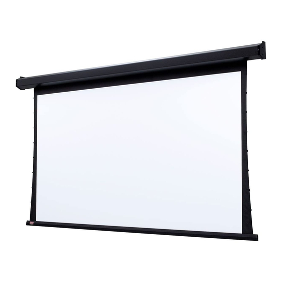
Premier
Electrically operated projection screen with motor-in-roller
Overview - Components
Junction Box
Section 1 - Removing Shipping Brackets
CAUTION: Shipping support brackets must be removed from bracket
clamps at each end of dowel before initial operation, and before
screen is operated in UP direction.
CAUTION: Raise and lower viewing surface several times to confirm
satisfactory operation. If viewing surface does not operate properly,
turn power off and check electrical connections.
Read and understand all warnings
Contents
Overview - Components ...............................................................................................1
Section 1 - Removing Shipping Brackets
Section 2 - Electrical Connections .............................................................................2
Section 3 - Operation....................................................................................................2
PLEASE READ - Safety Information ............................................................................2
Section 4 - Hanging Screen and Methods of Installation .......................................3
Cable
Exit
(without cover)
Tension
Cable
(Figure 1)
..................................................1
Dowel
1. Remove
1. Remove fasteners
fasteners
from bracket clamps.
from
bracket clamps.
4. Retighten dowel
4. Retighten dowel
endcap screws.
endcap screws.
CAUTION
before beginning installation.
(Page 2 of this document)
Section 5 - Limit Adjustments .....................................................................................4
Section 6 - Tab-Tension Adjustment Procedure ......................................................4
Section 8 - Dimensions ................................................................................................5
Section 9 - Wiring Diagrams: Standard and Quiet Motor .......................................6
INSTRUCTIONS
INSTALLATION & OPERATION
Figure 1
2. Run the screen
2. Run the screen
DOWN to expose
DOWN to expose
dowel screws.
dowel screws.
3. Loosen screws
and remove
shipping bracket.
.........................5
If you have any difficulties installing or servicing your
Premier projection screen, call your dealer or Draper, Inc.
Draper, Inc. | 411 S. Pearl St. Spiceland, IN 47385
draperinc.com | 765.987.7999 | 800.238.7999
|
FORM: Premier_Inst20
© 2020 All Rights Reserved
TOOLS
REQUIRED
PENCIL
POWER DRILL
TAPE MEASURE
LEVEL
HARDWARE
(by others)
Advertisement
Table of Contents

Related Manuals for Draper Premier


Summary of Contents for Draper Premier
- Page 1 Section 10 - Wiring Diagrams: Motor with internal low-voltage controller ..7 If you have any difficulties installing or servicing your Premier projection screen, call your dealer or Draper, Inc. Draper, Inc. | 411 S. Pearl St. Spiceland, IN 47385 draperinc.com | 765.987.7999 | 800.238.7999 FORM: Premier_Inst20 ©...
- Page 2 Important Safety Information Improper installation and use of the Premier screen can result in serious injury or death. Primarily, injuries can occur if the unit falls due to imprecise installation, mishandling of the unit during installation, or installation on an insufficient wall, or ceiling structure. Please use extreme care.
- Page 3 Premier page 3 of 7 Installation Closeup Fasteners for Section 4 - Hanging Screen and Methods of Installation wall mounting by others. S Hooks for CAUTION: Product is very heavy: Installer must provide adequate attachment hardware and anchors suspended as required. Installer must also ensure that structure is of adequate strength.
- Page 4 1. Raise screen surface approximately 1' above desired setting (30 cm) and turn off. Please check with Draper prior to resetting screen limits. 2. Turn DOWN limit screw clockwise (3 screw turns = 1/2 roller revolution) UP Limit 3.
- Page 5 Premier page 5 of 7 Section 7 - Accessing Internal Low-Voltage Control Unit (LVC-IV) PLEASE NOTE: Applies ONLY if Unit is built into case. Electrical Connection 1.. Locate LVC-IV Unit. Hole* 2. Remove the two star head screws from the motor end of the screen housing.
- Page 6 Premier page 6 of 7 Section 9 - Wiring Diagrams: Standard and Quiet Motor Please Note: Do not wire motors in parallel. 110-120V MOTOR AND QUIET MOTOR Single Station Control External LVC-IV Junction Box 2.214" Internal Screen Wiring 4.5" (56mm)
- Page 7 Premier page 7 of 7 Section 10 - Wiring Diagrams: Motor with internal low-voltage controller 110-120V MOTOR AND QUIET MOTOR 110-120V Motor Plug & Play 110-120V Motor (Motor with internal low-voltage controller) (Motor with internal low-voltage controller) (Internal Low-Voltage Controller for ILT motor)
Need help?
Do you have a question about the Premier and is the answer not in the manual?
Questions and answers