
Subscribe to Our Youtube Channel
Related Manuals for Omax M827S Series


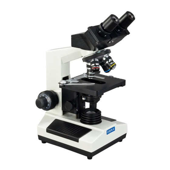
Summary of Contents for Omax M827S Series
- Page 1 User Manual Binocular Biological Compound Microscope Model M827S Series MicroscopeNet.com...
-
Page 2: Table Of Contents
Table of Contents i. Caution……..……………………………………………………………1 ii. Care and Maintenance……….………………………………….….…2 1. Component Illustration………………………….…………………..…3 2. Installation ……………………………………………………………...4 3. Operation...…………….……….………………………….…………..7 4. Specifications…………………….…………………………………..10 5. Optional Parts…………………….………………………….………..11 6. Troubleshooting Guide………….………………………….………..13 7. Darkfield Condenser Installation and Operation Instructions…...…15 8. Phase Contrast Kit Installation and Operation Instructions……..…17... -
Page 3: Caution
www.microscopenet.com i. Caution 1. Open the carton carefully with a knife or paper cutter. Find the “UP” sign and place the Styrofoam container on the side that makes the arrow upward. If the “UP” sign is missing, please open the Styrofoam container gently to prevent any accessory, i.e. -
Page 4: Care And Maintenance
www.microscopenet.com ii. Care and Maintenance 1. Do not attempt to disassemble any component including eyepieces, objectives or focusing assembly. 2. Keep the instrument clean; remove dirt and debris regularly. Accumulated dirt on metal surfaces should be cleaned with a damp cloth. More persistent dirt should be removed using a mild soap solution. -
Page 5: Component Illustration
www.microscopenet.com 1 Components Illustration Eyepiece Microscope Base Brightness Intensity Dial Diopter Ring Viewing Head Power Switch Eyepiece Tube Head Thumb Lock Screw Condenser Lock Thumb Knob Nosepiece Microscope Body Condenser Focus Knob Objective Focus Tension Ring Focus Stop Lever Slide Holder Coarse Focus Knob Abbe Condenser Mechanical Stage... -
Page 6: Installation
www.microscopenet.com 2 Installation 2.1 Installation of the binocular viewing head 1) Loosen the head thumb lock screw on the top of the microscope body and remove the plastic cover on the top. 2) Remove the cap on the dovetail of the binocular viewing head. 3) Seat the dovetail completely of the viewing head into the socket on the top of the microscope body and tighten the head thumb lock screw. - Page 7 www.microscopenet.com Color Filter Color Filter Holder Fig.2 2.5 Installing (or changing) the halogen bulb 1) Turn off the power switch and disconnect the power cord. 2) Allow some time to cool down the lamp. 3) Turn over the microscope on its side; find the bulb compartment at the bottom. 4) Open the cover of the bulb compartment by loosening the thumb screw.
- Page 8 www.microscopenet.com Fuse Holder Fig.4 Fuse Caution: Before you turn over the microscope, be sure to take the eyepieces off and be certain that the head is securely locked by the thumb screw. 2.7 Installing the mirror (optional, may not included in your package) 1) Turn off the power switch and disconnect the power cord.
-
Page 9: Operation
www.microscopenet.com 3 Operation 3.1 Adjusting illumination 1) Plug the power cord into the power socket on the microscope and connect it to the power outlet. 2) Turn on the power switch. 3) Rotate the brightness intensity dial to increase or decrease the brightness. Caution: A diffusion filter is attached beneath the condenser to get uniform light and protect your eyes from strong light when a low power objective applied. - Page 10 www.microscopenet.com 3) Use the fine focus knob to obtain a sharp image. 4) To get a good focused image, you may need to combine the focus knob adjustment and interpupillary distance adjustment, along with eyepiece diopter adjustment stated in 3.3 and 3.4. 5) You may now switch to another magnification objective.
- Page 11 www.microscopenet.com 3.7 Adjusting condenser 1) Turn the condenser focus knob to raise or lower the condenser. 2) Raise the condenser when using high power objectives and lower it when using low power objectives. Note: The centering of the condenser and the light axis of the objective are factory adjusted.
-
Page 12: Specifications
4 Specifications Model M827S series Total Magnification 40X, 80X, 100X, 200X, 400X, 800X, 1000X, 2000X Viewing Head Binocular, 45º inclined, 360º swiveling Interpupillary Distance Sliding adjustment, 2-3/16" ~ 2-15/16" (55mm-75mm) Diopter Adjustment On both eyepiece tubes Eyepieces 1 pair of WF10X/18... -
Page 13: Optional Parts
www.microscopenet.com 5 Optional Parts (The optional parts may be included in some models or sold separately.) 1) Darkfield Condensers Darkfield Numerical Mounting Model Objective Condenser Aperture Size(diameter) A191 0.7-0.9 37mm Plan 100X/1.25 oil-0.5 A191BD 1.36-1.25 37mm 160/0.17(spring) Plan 100X/1.25 oil-0.5 A191BOIL 1.36-1.25 160/0.17(spring), w/ iris... - Page 14 www.microscopenet.com 3) Phase Contrast Kits Centering Model Phase Contrast Objective Condenser Annular Ring Plates Telescope Plan achromatic 10X with five positions: built-in phase plate 10 for 10X phase contrast objective Plan achromatic 20X with 20 for 20X phase contrast built-in phase plate objective focusing 40 for 40X phase contrast...
-
Page 15: Troubleshooting Guide
www.microscopenet.com 6 Troubleshooting Guide GENERAL PROBLEMS Problem Cause Solution No electrical power Check power cord connection Lamp does not light Lamp bulb burnt out Replace bulb when switched on Fuse blown out Replace fuse Revolve the nosepiece to click-stop Revolving nosepiece not in click position by swinging the objective correctly Darkness at the stop position... - Page 16 www.microscopenet.com DARKFIELD PROBLEMS Problem Cause Solution The light is not on Turn on the light (A191BOIL, A191BD only) There Place a drop of oil on the top lens of is no oil in between the condenser condenser and let it contact the underside of top lens and slide, when using slide 100X objective...
-
Page 17: Darkfield Condenser Installation And Operation Instructions
www.microscopenet.com 7 Darkfield Condenser Installation and Operation Instructions Condenser Lock Condenser Holder 7.1 Dry darkfield condenser of A191 Thumb Screw 1) Mounting the dry darkfield condenser Loosen the condenser lock thumb screw on the condenser holder and remove the brightfield condenser. - Page 18 www.microscopenet.com 3) When using the 40X objective to observe the specimen Place the slide on the stage. Lower the condenser until a sharp brightfield image showing in the viewing field. Raise the condenser until the darkfield image showing in the viewing field. 4) When using the 100X objective to observe the specimen ...
-
Page 19: Phase Contrast Kit Installation And Operation Instructions
www.microscopenet.com 8 Phase Contrast Kit Installation and Operation Instructions 8.1 Phase contrast kits of A1PHB1 or A1PHB3: 1) Mounting the phase contrast objectives a. Take off all the objectives from the nosepiece. b. Install the phase contrast objectives onto the nosepiece following the steps in 2.3. - Page 20 www.microscopenet.com shown in Fig.19 (c), hold the ring plate from the bottom of the annular ring disk and adjust its position until two ring images are coincided. f. Remove the centering telescope and replace it with the eyepiece. g. Put the specimen on the stage and adjust the illumination, focusing, etc following the instructions in this manual.
- Page 21 www.microscopenet.com d. Observe from the telescope. The bright ring and dark ring should be coincided with each other as shown in Fig. 21 (d). e. If the ring images are not clear, turn the top of telescope until both ring images are in focus. f.
- Page 22 www.microscopenet.com e. Remove one eyepiece from the microscope eyepiece tube and insert the centering telescope. f. Turn the light of microscope on and observe from the telescope. g. Turn the top of the telescope (Fig.25) until the dark ring image is in focus. If the dark ring is hard to find, put a normal white print paper on the stage and under the objective then you will see the dark ring as shown in Fig.24 (a).
Need help?
Do you have a question about the M827S Series and is the answer not in the manual?
Questions and answers