
Related Manuals for Omax M8311Z Series


Summary of Contents for Omax M8311Z Series
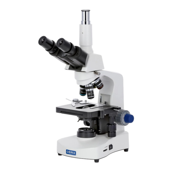
- Page 1 User Manual Trinocular Compound LED Microscope Model M8311Z Series MicroscopeNet.com...
-
Page 2: Table Of Contents
Table of Contents Caution ....................1 Care and Maintenance ................2 Components Illustration ................ 3 Installation ..................... 4 Operation ....................6 Specifications ..................9 Optional Parts ..................10 Troubleshooting Guide ................ 13 Darkfield Condenser Installation and Operation Instructions ....15 Phase Contrast Kit Installation and Operation Instructions .... -
Page 3: Caution
www.microscopenet.com i. Caution 1. Open the carton carefully with a knife or paper cutter. Find the “UP” sign and place the Styrofoam container on the side that makes the arrow upward. If the “UP” sign is missing, please open the Styrofoam container gently to prevent any accessory items (i.e. -
Page 4: Care And Maintenance
www.microscopenet.com ii. Care and Maintenance 1. Do not attempt to disassemble any component including eyepieces, objectives or focusing assembly. 2. Keep the instrument clean; remove dirt and debris regularly. Accumulated dirt on metal surfaces should be cleaned with a damp cloth. More persistent dirt should be removed using a mild soap solution. -
Page 5: Components Illustration
www.microscopenet.com 1. Components Illustration Photo Tube Microscope Base Power Switch Eyepiece Head Lock Thumb Screw Brightness Intensity Dial Diopter Ring Nosepiece Condenser Lock Thumb Screw Eyepiece Tube Objective Condenser Focus Knob Viewing Head Microscope Body Condenser Slide Holder Coarse Focus Knob Color Filter Holder Mechanical Stage Fine Focus Knob... -
Page 6: Installation
www.microscopenet.com 2. Installation 2.1 Installation of the trinocular viewing head 1) Loosen the head lock thumb screw on the top of the microscope body and remove the plastic cover on the top. 2) Remove the cap on the dovetail of the trinocular viewing head. 3) Seat the dovetail of the viewing head into the socket on the top of the microscope body and tighten the head lock thumb screw. - Page 7 www.microscopenet.com 2.5 Installation of the glass filter 1) Swing out the color filter holder under the condenser. 2) Place the filter into the color filter holder as shown in Fig. 2, swing the holder in. Color Filter Color Filter Holder Fig.2 2.6 Replacing the fuse 1) Turn off the power switch and disconnect the power cord.
-
Page 8: Operation
www.microscopenet.com 3. Operation 3.1 Adjusting illumination 1) Plug the power cord into the power socket on the microscope and connect it to the power outlet. 2) Turn on the power switch. 3) Rotate the brightness intensity dial to increase or decrease the brightness of the illuminator. - Page 9 www.microscopenet.com 2) Then observe the specimen with your left eye only through the left eyepiece. If the specimen is not in focus, turn the diopter ring on the eyepiece tube until a sharp image is obtained. 3.6 Applying the immersion oil 1) Rotate the objective nosepiece to seat the observing position between the 40X and 100X objectives as shown in Fig.
- Page 10 www.microscopenet.com Note: The iris diaphragm is designed to adjust the aperture size, not to adjust the brightness although the brightness will be changed when it's adjusted. When aperture is adjusted to smaller size, the contrast will be increased and the depth of field will be increased as well.
-
Page 11: Specifications
4. Specifications General Model M8311Z series Total Magnification 40X, 100X, 250X, 400X, 1000X, 2500X 30º inclined, 360º swiveling Siedentopf trinocular viewing head Interpupillary distance 1-7/8” ~ 2-15/16” (48mm ~ 75mm) Viewing Head Adjustable diopter on left eyepiece tubes 1 pair of WF10X/18... -
Page 12: Optional Parts
www.microscopenet.com 5. Optional Parts (The optional parts may be included in some models or sold separately.) 1) Cameras Model Sensor Resolution Operating System Software MS Windows A1502 640 x 480 (0.3MP) Mac OS X 10.6-10.8 A3513U 1280 x 1024 (1.3MP) A3520U 1600 x 1200 (2.0MP) A3530U... - Page 13 www.microscopenet.com 2) Darkfield Condensers Darkfield Numerical Mounting Model Objective Condenser Aperture Size(diameter) A191 0.7-0.9 37mm A191BD 1.36-1.25 37mm Plan 100X/1.25 oil-0.5 A191BOIL 1.36-1.25 160/0.17(spring), with 37mm (new design) iris diaphragm 3) Carrying Case Model Dimension Net Weight 9-7/8" x 11" x 18-1/2" A187V 2 lb 6 oz (1.1 kg) (25cm x 28cm x 47cm)
- Page 14 www.microscopenet.com 4) Phase Contrast Kits Centering Model Objectives Condenser Annular Ring Plates Telescope Plan achromatic 10X with five positions: built-in phase plate 10 for 10X phase contrast objective Plan achromatic 20X with 20 for 20X phase contrast built-in phase plate objective Plan achromatic 40X with 40 for 40X phase contrast...
-
Page 15: Troubleshooting Guide
www.microscopenet.com 6. Troubleshooting Guide GENERAL PROBLEMS Problem Cause Solution No electrical power Check power cord connection Lamp does not light LED or power unit dead Contact seller for service when switched on Fuse blown out Replace fuse Darkness at the Revolve the nosepiece to click-stop periphery or uneven Revolving nosepiece not in click stop... - Page 16 www.microscopenet.com Increase the tension on the focusing Slippage of focus Tension adjustment is set too low knobs when using the coarse focusing knob Fine Loosen the tension on the focusing focus is ineffective Tension adjustment is set too high knobs DARKFIELD PROBLEMS Problem Cause...
-
Page 17: Darkfield Condenser Installation And Operation Instructions
www.microscopenet.com 7. Darkfield Condenser Installation and Operation Instructions Dry darkfield condenser of A191 Condenser Lock Condenser Holder 1) Mounting the dry darkfield condenser Thumb Screw Loosen the condenser lock thumb screw on the condenser holder and remove the brightfield condenser. -
Page 18: Phase Contrast Kit Installation And Operation Instructions
www.microscopenet.com 3) Raise the condenser till the top lens is close to the opening of stage. Place a drop of immersion oil on the top of the lens of the condenser. 4) Place the slide on the stage. Raise the condenser and let the oil drop contact the bottom of the slide. - Page 19 www.microscopenet.com 20 as shown in Fig. 15. 5) Centering the annular ring. a. Remove one eyepiece from the microscope eyepiece tube and insert the centering telescope as shown in Fig. 16. b. Observe from the telescope. The bright ring and dark ring should be coincided with each other as shown in Fig.17 (d).
- Page 20 www.microscopenet.com Condenser Lock Thumb Screw Condenser Holder Fig.18 Note: There are 2 phase contrast objectives: 10X and 40X, and there are 2 condenser annular rings on the sliding selector: 10/20 and 40. The corresponding objective, annular ring and iris diagram must work together, i.e., 40X phase contrast objective must work with 40 condenser annular ring and iris diagram 40 and so on.
- Page 21 www.microscopenet.com Note: The darkfield condenser works with the 4X, 10X, 40X regular brightfield objectives. The darkfield condenser does not work with the regular 100X oil immersion objective. The darkfield condenser works with the 100X oil darkfield objective with iris diaphragm AJ100PR (sold separately). ...
- Page 22 www.microscopenet.com Note: There are 3 phase contrast objectives: 10X, 40X and 100X, and there are 3 condenser ring plates: 10X, 40X and 100X. The corresponding objective and ring plate must work together, i.e. 10X phase contrast objective must work with 10X condenser ring plate, and so on.
Need help?
Do you have a question about the M8311Z Series and is the answer not in the manual?
Questions and answers
I have the Model M8311Z Omax microscope with the A1PHC2 condenser kit. As you know, the condenser kit mounts inside a ring on the underside of the microscope. That mounting ring itself on the microscope is held in place by three set screws. On my microscope, these screws are not tight, so when I mount the A1PHC2 condenser kit, it is loose, even though the thumb screw is completely tight. This wobble makes the phase contrast and the dark field modes unusable. How do I stabilize this? It would seem precise alignment is required since the dark field plate is not adjustable, it would seem these set screws would determine the position of the darkfield plate. What do you suggest? How can I get this to work? Thanks, Paul
To stabilize the mounting ring and ensure the A1PHC2 condenser kit is securely attached and functions properly on the Omax M8311Z microscope, follow these steps:
1. Remove the original condenser by loosening the condenser lock thumb screw and taking it off the holder.
2. Insert the A1PHC2 phase contrast condenser into the condenser holder.
3. Tighten the condenser lock thumb screw to secure the condenser in place.
Ensure the correct phase contrast objective (10X, 40X, or 100X) matches the corresponding condenser ring plate for proper function.
This answer is automatically generated