Table of Contents
Advertisement
Quick Links
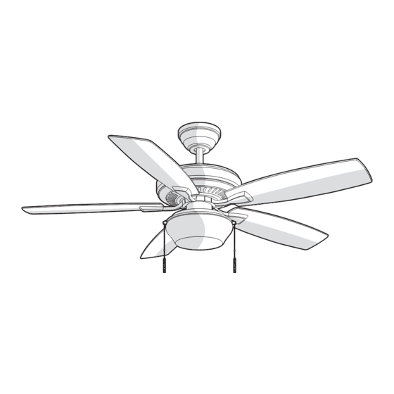
USE AND CARE GUIDE
GAZEBO II 52 IN. CEILING FAN
Questions, problems, missing parts? Before returning to the store,
call Hampton Bay Customer Service
8 a.m. - 7 p.m., EST, Monday-Friday, 9 a.m. - 6 p.m., EST Saturday
1-855-HD-HAMPTON
HAMPTONBAY.COM
Visual instruction of how to install this fan:
Visit www.homedepot.com and enter either the Item or Model number to nd
this fan and click the link of visual instruction in the product overview section.
THANK YOU
Item #1002 498 557
#1002 498 571
Model # YG188-BN
# YG188-WB
Advertisement
Table of Contents

Related Manuals for HAMPTON BAY 1002 498 557


Summary of Contents for HAMPTON BAY 1002 498 557
- Page 1 Item #1002 498 557 #1002 498 571 Model # YG188-BN # YG188-WB USE AND CARE GUIDE GAZEBO II 52 IN. CEILING FAN Questions, problems, missing parts? Before returning to the store, call Hampton Bay Customer Service 8 a.m. - 7 p.m., EST, Monday-Friday, 9 a.m. - 6 p.m., EST Saturday 1-855-HD-HAMPTON HAMPTONBAY.COM...
-
Page 2: Table Of Contents
Table of Contents Table of Contents ............Operation ..............Pull Chain Operating Instructions .......... Safety Information ............Reverse Switch Operating Instructions ........Warranty ................. Care and Cleaning ............Pre-Installation .............. Troubleshooting ............Service Parts ..............Tools Required ................. Hardware Included ..............Package Contents .............. -
Page 3: Safety Information
Safety Information To reduce the risk of electric shock, ensure electricity has However, there is no guarantee that interference will not occur been turned off at the circuit breaker or fuse box before in a particular installation. If this equipment does cause harmful beginning. -
Page 4: Warranty
Warranty The manufacturer warrants the fan motor to be free from defects in workmanship and material present at time of shipment from the factory for a period of lifetime after the date of purchase by the original purchaser. The manufacturer warrants the light kit (excluding any glass), to be free from defects in workmanship and material at the time of shipment from the factory for a period of three years after the date of purchase by the original purchaser. -
Page 5: Hardware Included
Pre-Installation (continued) HARDWARE INCLUDED HARDWARE INCLUDED NOTE: Hardware not shown to actual size. Part Part Description Description Quantity Quantity Plastic wire nut Canopy mounting screws with lock washer (preassembled) Blade attachment screw and rubber washer Blade arm screw and lock washer (preassembled) Clevis pin (preassembled) Cotter pin (preassembled) Collar setscrew (preassembled) -
Page 6: Package Contents
Pre-Installation (continued) PACKAGE CONTENTS PACKAGE CONTENTS Part Part Description Description Quantity Quantity Part Part Description Description Quantity Quantity Mounting bracket (preassembled) Fan motor assembly Canopy ring (preassembled) Blade Canopy Blade arm Canopy bottom cover (preassembled) Light kit Hanger ball/downrod assembly Glass shade Coupling cover... -
Page 7: Dual Mounting Instructions
Pre-Installation (continued) DUAL MOUNTING INSTRUCTIONS DUAL MOUNTING INSTRUCTIONS This ceiling fan is supplied with two types of hanging assemblies: the standard ceiling installation using the downrod with ball and socket mounting, and the "close-to-ceiling" mounting. The "close-to-ceiling" mounting is recommended in rooms with less than 8 ft. ceilings or in areas where additional space is desired from the floor to the fan blades. -
Page 8: Installation
Installation MOUNTING OPTIONS MOUNTING OPTIONS WARNING: To reduce the risk of fire, electric shock, or NOTE: You may need a longer downrod to maintain proper blade clearance when installing on a steep, sloped ceiling. personal injury, mount the fan to an outlet box marked acceptable for fan support using the screws provided with the The maximum angle allowable is 18°... -
Page 9: Assembly
Assembly — Standard Ceiling Mounting Preparing the canopy Preparing the motor □ □ Remove the canopy ring (B) from the canopy (C). Remove the cotter pin (FF) and clevis pin (EE), and loosen the two collar setscrews (GG) from the fan □... -
Page 10: Close-To-Ceiling Mounting
Assembly — Close-to-Ceiling Mounting Preparing the canopy Preparing the motor □ □ Remove the canopy ring (B) from the canopy (C). Remove the cotter pin (FF), clevis pin (EE) and the two collar setscrews (GG) from the motor collar. □ Remove the mounting bracket (A) from the canopy (C) by loosening the four canopy mounting screws with □... -
Page 11: Hanging The Fan
Assembly — Hanging the Fan Attaching the fan to the electrical box WARNING: To reduce the risk of fire, electric shock or other personal injury, mount the fan only to an outlet box or supporting system marked acceptable for fan support and use the mounting screws provided with the outlet box. - Page 12 Assembly — Hanging the Fan (continued) Making the electrical connections Ground conductor Neutral WARNING: To avoid possible electrical shock, be sure electricity is turned off at the main fuse box before wiring. Black White WARNING: Check to see that all connections are tight, including ground, and that no bare wire is visible at the wire nuts (except for the ground wire).
- Page 13 Assembly — Hanging the Fan (optional) Single Switch Connections Dual Switch Connections □ On a single switch the fan and light can be turned on or On a dual switch the fan and light can be turned on or off off together.
- Page 14 Assembly — Hanging the Fan (continued) Standard ceiling mounting Close-to-ceiling mounting WARNING: Make sure the tab on the mounting bracket (A) WARNING: Locking slots of the canopy (C) are provided properly sits in the groove in the hanger ball (E) before only as an aid to mounting.
-
Page 15: Attaching The Fan Blades
Assembly — Attaching the Fan Blades Removing the rubber Attaching the blades to packing mounts the blade arms □ □ The fan motor assembly (G) is shipped with rubber Attach the blades (H) to the blade arms (I) using the three blade attachment screws and rubber washers packing mounts (PP) to prevent movement during (CC). -
Page 16: Installing The Light Kit
Assembly — Installing the Light Kit Attaching the light kit to Installing the light bulb the switch housing and glass shade CAUTION: Before starting installation, disconnect the NOTE: If you do not wish to install the light kit, skip steps power by turning off the circuit breaker or removing the fuse 11 through 12 and proceed to step 13. -
Page 17: Operation
Assembly — Installing the Light Kit (continued) Installing the fan without the light kit (Optional) □ Disassemble the switch housing cover (WW) from the light kit (J). You can keep the light kit (J) for future use. □ Attach the plastic plug (LL) to the switch housing cover (WW). -
Page 18: Reverse Switch Operating Instructions
Operation (continued) REVERSE SWITCH OPERATING INSTRUCTIONS REVERSE SWITCH OPERATING INSTRUCTIONS The reverse switch is located on the surface of the switch housing. This switch controls directions: forward (switch down) or reverse (switch up). NOTE: Wait for the fan to stop before reversing the direction of the blade rotation. -
Page 19: Troubleshooting
Troubleshooting WARNING: Make sure the power is off at the electrical panel box before you attempt any repairs. Refer to step 6 “Making the electrical connections” on page 12. Problem Problem Solution Solution □ Check the main and branch circuit fuses or breakers. The fan will not start. -
Page 20: Service Parts
Service Parts Part Part Description Description Part Part Description Description Mounting bracket (preassembled) Plastic wire nut Canopy ring (preassembled) Canopy mounting screws with lock washer (preassembled) Canopy Blade attachment screw and rubber washer Canopy bottom cover (preassembled) Blade arm screw and lock washer (preassembled) Hanger ball/downrod assembly Clevis pin (preassembled) Coupling cover... - Page 21 Questions, problems, missing parts? Before returning to the store, call Hampton Bay Customer Service 8 a.m. - 7 p.m., EST, Monday-Friday, 9 a.m. - 6 p.m., EST Saturday 1-855-HD-HAMPTON HAMPTONBAY.COM Retain this manual for future use.
Need help?
Do you have a question about the 1002 498 557 and is the answer not in the manual?
Questions and answers