Table of Contents
Advertisement
Advertisement
Table of Contents

Related Manuals for GW Instek GPE-1326 Series


Summary of Contents for GW Instek GPE-1326 Series
- Page 1 Multi-output DC Power Supply GPE-1326/2323/3323/4323 Series USER MANUAL GW INSTEK PART NO. 82GP343230E01 99 Washington Street Melrose, MA 02176 Phone 781-665-1400 Toll Free 1-800-517-8431 Visit us at www.TestEquipmentDepot.com ISO-9001 CERTIFIED MANUFACTURER...
- Page 2 This manual contains proprietary information, which is protected by copyrights. All rights are reserved. No part of this manual may be photocopied, reproduced or translated to another language without prior written consent of Good Will company. The information in this manual was correct at the time of printing. However, Good Will continues to improve products and reserves the rights to change specification, equipment, and maintenance procedures at any time without notice.
-
Page 3: Table Of Contents
TABLE OF CONTENTS Table of Contents SAFETY INSTRUCTIONS ..........5 OVERVIEW ..............10 Introduction ......... 10 Series Lineup / Main Features ..... 12 Principle of Operation ......13 Front Panel Overview ......15 Rear Panel Overview ......23 CV/CC Crossover Characteristics ..24 SETUP ................ - Page 4 GPE-1326/2323/3323/4323 Series User Manual APPENDIX ..............45 Fuse Replacement ........ 45 Specifications ........46 Declaration of Conformity ....48 INDEX ................49...
-
Page 6: Safety Guidelines
GPE-1326/2323/3323/4323 Series User Manual Do not dispose electronic equipment as unsorted municipal waste. Please use a separate collection facility or contact the supplier from which this instrument was purchased. Safety Guidelines Do not place any heavy object on the device. General ... -
Page 7: Safety Instructions
SAFETY INSTRUCTIONS Fuse type: Fuse 100V/120V: T6.3A/250V 220V/230V: T3.15A/250V WARNING Make sure the correct type of fuse is installed before power up. To ensure fire protection, replace the fuse only with the specified type and rating. Disconnect the power cord before fuse ... - Page 8 GPE-1326/2323/3323/4323 Series User Manual (Pollution Degree) EN 61010-1:2010 specifies the pollution degrees and their requirements as follows. The GPE-1326/2323/3323/4323 series falls under degree 2. Pollution refers to “addition of foreign matter, solid, liquid, or gaseous (ionized gases), that may produce a reduction of dielectric strength or surface resistivity”.
- Page 9 SAFETY INSTRUCTIONS Power cord for the United Kingdom When using the GPE-1326/2323/3323/4323 series in the United Kingdom, make sure the power cord meets the following safety instructions. NOTE: This lead/appliance must only be wired by competent persons WARNING: THIS APPLIANCE MUST BE EARTHED IMPORTANT: The wires in this lead are coloured in accordance with the following code: Green/ Yellow:...
-
Page 10: Overview
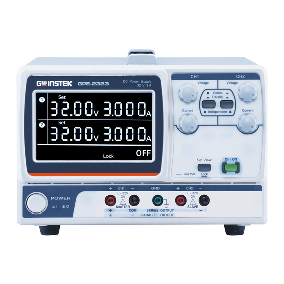
GPE-1326/2323/3323/4323 Series User Manual VERVIEW This chapter describes the GPE-1326/ 2323/ 3323/ 4323 series in a nutshell, including its main features and front/ rear panel introduction. After going through the overview, follow the Setup chapter (page 25) to properly power up and set operation environment. - Page 11 OVERVIEW The three output modes of GPE-2323/3323/4323 Independent / series, independent, series tracking and parallel Series Tracking / Parallel Tracking tracking can be selected through pressing the TRACKING key on the front panel. In the independent mode, the output voltage and current of each channel are controlled separately.
-
Page 12: Series Lineup / Main Features
GPE-1326/2323/3323/4323 Series User Manual The front panel display (CH1, CH2) shows the Automatic output voltage or current. When operating in the tracking mode tracking mode, the power supply will automatically connect to the auto- tracking mode. For more details about CH1/CH2 Series Tracking Mode, see page 38 Series Lineup / Main Features Main Features... -
Page 13: Principle Of Operation
OVERVIEW Principle of Operation The power supply consists of the following. Overview AC input circuit Transformer Bias power supply including rectifier, filter, pre-regulator and reference voltage source Main regulator circuit including the main rectifier and filter, series regulator, current comparator, voltage comparator, reference voltage amplifier, remote device and relay control circuit... - Page 14 GPE-1326/2323/3323/4323 Series User Manual Auxiliary Rectifier The auxiliary rectifiers D120~ D123 provide bias voltage filtered by the capacitors C120 and C121, for the pre-regulators U150 and U151. They provide a regulated voltage for other modules. The main rectifier is a full wave bridge rectifier. It Main Rectifier provides the power after the rectifier is filtered by the capacitor C101, and then regulated via a series-...
- Page 18 GPE-1326/2323/3323/4323 Series User Manual When the output current is over Output status of range, the overloaded indicator CH3 in the GPE- 3323 will be lit on the LCD Overload display.
- Page 21 OVERVIEW Output voltage and current The GPE-1326 Output terminal Remote sense terminals The GPE-1326 Sense terminal...
-
Page 24: Cv/Cc Crossover Characteristics
GPE-1326/2323/3323/4323 Series User Manual CV/CC Crossover Characteristics The GPE-1326/2323/3323/4323 series automatically Background switch between constant voltage mode (CV) and constant current mode (CC), according to load condition. When the current level is smaller than the output CV mode setting, the GPE-1326/2323/3323/4323 series operates in Constant Voltage mode. -
Page 29: Setting Voltage Lock From Front Panel
SETUP Setting Voltage Lock from Front Panel The lock function of the GPE-1326/ 2323/ 3323/ Background / 4323 series can be used when you need to keep the Connection output voltage constant to avoid the load from being damaged due to inadvertent operation. The voltage lock takes the present channel settings as the reference levels. -
Page 30: Set The Displayed Digit Resolution For The Voltage/Current
GPE-1326/2323/3323/4323 Series User Manual Panel operation 1. Press and hold the Output key and turn on the power until the icon flashes on the LCD display. 2. Press the “Set View” key to select. 3. Press the “ON/OFF” key to ... -
Page 31: Remote Control Setting
SETUP Remote Control Setting Through the "Remote Control" terminal, the GPE- Background / 1326/2323/3323/4323 series can turn the power on Connection or off. ON/OFF setting Remote control setting Panel operation 1. Short pins 7 and 8 (remote control setting). This will put the power state (ON/OFF) under remote control. -
Page 35: Operation
OPERATION You can check the setting of the GPE-4323 by using the CH2/CH3 key to toggle to CH3(③ appears on the LCD display). 3. Press the Output key to turn on the output. The Output key will be lit. GPE-3323: When the output OVERLOAD Overload... -
Page 37: Constant Current
OPERATION You can use the CH1/CH4 key to toggle to CH4(④) appears on the LCD display) to check the setting value. 3. Press the Output key to turn on the output. The Output key will be lit. CV →... -
Page 41: Output Voltage
OPERATION 3. Use the CH1 voltage knob to set the master & slave output voltage (the same level for both channels). 4. Use the CH1 current knob to set the master output current. 5. Use the CH2 current knob to ... - Page 43 OPERATION 3. Use the CH1 voltage and current knobs to set the output voltage and current. CH2 control function is disabled. 4. Press the Output key to turn on the output. The Output key will be lit. 5.
-
Page 44: Faq
GPE-1326/2323/3323/4323 Series User Manual Q1. I pressed the panel lock key but the output still turns on/off. A1. For safety reasons the output key is not affected by the panel key lock feature. Q2. The CH3 overload indicator turned on – is this an error? A2. - Page 49 INDEX NDEX Automatic out off ....27 Block diagram ....13 Banana plug ......26 List of features ....12 Caution symbol....... 5 Operation theory ....13 CC/CV ........35 Technology overview ..10 CC/CV indicator ....37 Ground symbol ...... 5 Cleaning the instrument ..
- Page 50 GPE-1326/2323/3323/4323 Series User Manual Tracking mode Warning symbol ....5 Operation theory ....11 Wire, load......26 UK power cord ....... 9 99 Washington Street Melrose, MA 02176 Phone 781-665-1400 Toll Free 1-800-517-8431 Visit us at www.TestEquipmentDepot.com...
Need help?
Do you have a question about the GPE-1326 Series and is the answer not in the manual?
Questions and answers