Sign In
Upload
Download
Table of Contents
Contents
Add to my manuals
Delete from my manuals
Share
URL of this page:
HTML Link:
Bookmark this page
Add
Manual will be automatically added to "My Manuals"
Print this page
×
Bookmark added
×
Added to my manuals
Manuals
Brands
GW Instek Manuals
Power Supply
GPS-1830
User manual
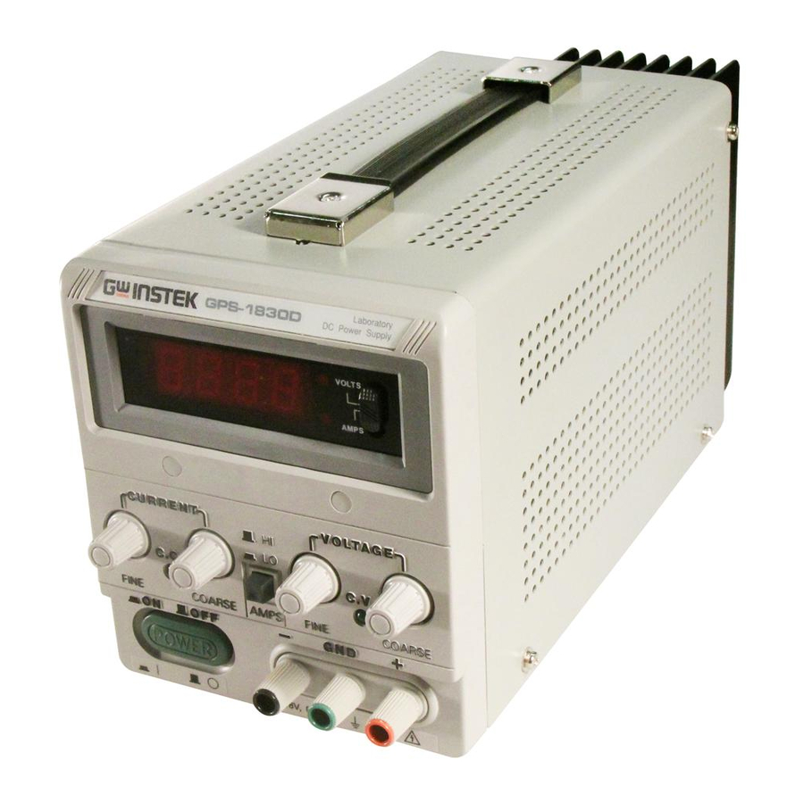
GW Instek GPS-1830 User Manual
Dc power supply analog and digital series
Hide thumbs
Also See for GPS-1830
:
User manual
(22 pages)
1
Table Of Contents
2
3
4
5
6
7
8
9
10
11
12
13
14
15
16
17
18
19
20
page
of
20
Go
/
20
Contents
Table of Contents
Bookmarks
Table of Contents
Introduction
Table of Contents
Specifications
2-1 General
Constant Voltage Operation
Constant Current Operation
Indicator Meter
Insulation
Theory of Operation
Panel Controls and Indicators
Front Panel
Rear Panel
Operation Instructions
Precaution
Constant Voltage/Constant Current Characteristic
Crossover Point
Voltage Output
Output Current
Operation Mode
Fuse Replacement
Line Voltage Conversion
Adjustments
Cleaning
Advertisement
Quick Links
1
Introduction
2
Table of Contents
3
Specifications
4
Constant Voltage Operation
5
Constant Current Operation
6
Front Panel
7
Voltage Output
8
Operation Mode
Download this manual
DC POWER
S U P P L Y
Tenma Models 72-2005 and 72-6535
(Analog and Digital Series)
User Manual
Table of
Contents
Previous
Page
Next
Page
1
2
3
4
5
Advertisement
Table of Contents
Need help?
Do you have a question about the GPS-1830 and is the answer not in the manual?
Ask a question
Questions and answers
Related Manuals for GW Instek GPS-1830
Power Supply GW Instek GPS-S Series User Manual
Analog/digital type (22 pages)
Power Supply GW Instek GPS-2303 User Manual
Multi-output dc power supply (17 pages)
Power Supply GW Instek GPS-2303 User Manual
Multi-output d.c. power supply (18 pages)
Power Supply GW Instek GPS-3030DD User Manual
Analog/digital type (22 pages)
Power Supply GW Instek GPD-3303 Series User Manual
Gpd-3303 series dc power supply (26 pages)
Power Supply GW Instek GPE-1326 Series User Manual
Multi-output dc power supply (50 pages)
Power Supply GW Instek GPE-1326 Series User Manual
Multi-output dc power supply (49 pages)
Power Supply GW Instek GPP-1326 User Manual
Programmable dc power supply (200 pages)
Power Supply GW Instek GPP-2323 User Manual
Programmable (208 pages)
Power Supply GW Instek GPP-3323 User Manual
Programmable dc power supply (208 pages)
Power Supply GW Instek GPP-3060 User Manual
Programmable dc power supply (218 pages)
Power Supply GW Instek GPP-3650 User Manual
Programmable dc power supply (215 pages)
Power Supply GW Instek GPP-3610H User Manual
Programmable dc power supply (197 pages)
Power Supply GW Instek GPC-6030 User Manual
Analog / digital type dc power supply (30 pages)
Power Supply GW Instek GPC-3060 User Manual
Analog / digital type dc power supply (30 pages)
Power Supply GW Instek GPC-6030D User Manual
Analog / digital type dc power supply (30 pages)
This manual is also suitable for:
Gps-1830d
Gps-1850d
Gps-1850
G ps-3030d
Gps-6010
Gps-3030
...
Show all
72-2005
72-6535
Gps-3030d
Table of Contents
Save PDF
Print
Rename the bookmark
Delete bookmark?
Delete from my manuals?
Login
Sign In
OR
Sign in with Facebook
Sign in with Google
Upload manual
Upload from disk
Upload from URL


Need help?
Do you have a question about the GPS-1830 and is the answer not in the manual?
Questions and answers