
Related Manuals for GW Instek GPD-303S Series


Summary of Contents for GW Instek GPD-303S Series
- Page 1 All manuals and user guides at all-guides.com DC Power Supply GPD-X303S Series USER MANUAL GW INSTEK PART NO. 82PD-433S0M01 ISO-9001 CERTIFIED MANUFACTURER...
- Page 2 All manuals and user guides at all-guides.com This manual contains proprietary information, which is protected by copyrights. All rights are reserved. No part of this manual may be photocopied, reproduced or translated to another language without prior written consent of Good Will company. The information in this manual was correct at the time of printing.
-
Page 3: Table Of Contents
All manuals and user guides at all-guides.com TABLE OF CONTENTS Table of Contents SAFETY INSTRUCTIONS ........... 5 OVERVIEW ..............10 Introduction......... 10 Series Lineup / Main Features ..... 13 Principle of Operation......14 Front Panel Overview ......16 Rear Panel Overview ......21 CV/CC Crossover Characteristics .. - Page 4 All manuals and user guides at all-guides.com GPD-X303S Series User Manual Remote Connection Step ...... 44 Command Syntax ......... 46 Error Messages ........46 Command List........47 Command Details ........ 48 FAQ ................53 APPENDIX ..............54 Fuse Replacement ........ 54 Specifications ........
-
Page 5: Safety Instructions
All manuals and user guides at all-guides.com SAFETY INSTRUCTIONS AFETY INSTRUCTIONS This chapter contains important safety instructions that you must follow when operating the GPD- X303S series and when keeping it in storage. Read the following before any operation to insure your safety and to keep the best condition for the GPD- X303 series. - Page 6 All manuals and user guides at all-guides.com GPD-X303S Series User Manual Do not dispose electronic equipment as unsorted municipal waste. Please use a separate collection facility or contact the supplier from which this instrument was purchased. Safety Guidelines Do not place any heavy object on the GPD- General •...
- Page 7 All manuals and user guides at all-guides.com SAFETY INSTRUCTIONS Fuse type: 100V/120V: T6.3A/250V, Fuse • 220V/230V: T3.15A/250V WARNING Make sure the correct type of fuse is installed • before power up. To ensure fire protection, replace the fuse only • with the specified type and rating.
- Page 8 All manuals and user guides at all-guides.com GPD-X303S Series User Manual (Pollution Degree) EN 61010-1:2001 specifies the pollution degrees and their requirements as follows. The GPD-X303S series falls under degree 2. Pollution refers to “addition of foreign matter, solid, liquid, or gaseous (ionized gases), that may produce a reduction of dielectric strength or surface resistivity”.
- Page 9 All manuals and user guides at all-guides.com SAFETY INSTRUCTIONS Power cord for the United Kingdom When using the GPD-2303S/GPD-3303S/GPD-4303S series in the United Kingdom, make sure the power cord meets the following safety instructions. NOTE: This lead/appliance must only be wired by competent persons WARNING: THIS APPLIANCE MUST BE EARTHED IMPORTANT: The wires in this lead are coloured in accordance with the following code:...
-
Page 10: Overview
All manuals and user guides at all-guides.com GPD-X303S Series User Manual VERVIEW This chapter describes the GPD-2303S/GPD- 3303S/GPD-4303S series in a nutshell, including its main features and front / rear panel introduction. After going through the overview, follow the Setup chapter (page23) to properly power up and set operation environment. - Page 11 All manuals and user guides at all-guides.com OVERVIEW The three output modes of GPD-X303S series, Independent / Tracking Series / independent, tracking series, and tracking parallel, Tracking Parallel can be selected through pressing the TRACKING key on the front panel. In the independent mode, the output voltage and current of each channel are controlled separately.
- Page 12 All manuals and user guides at all-guides.com GPD-X303S Series User Manual When used in audio production lines, the power Dynamic load supply can provide a continuous or dynamic load using a jumper connector (JP101/JP401). When the jumper connectors are connected to the “ON” position (shorted), a stable DC current power will be provided for audio power amplifiers.
-
Page 13: Series Lineup / Main Features
All manuals and user guides at all-guides.com OVERVIEW Series Lineup / Main Features Main Features Low noise: Temperature controlled cooling fan Performance • Compact size, light weight • Constant Voltage / Constant Current operation Operation • Tracking Series / Tracking parallel operation •... -
Page 14: Principle Of Operation
All manuals and user guides at all-guides.com GPD-X303S Series User Manual Principle of Operation The power supply consists of the following. Overview AC input circuit • Transformer • Bias power supply including rectifier, filter, • pre-regulator and reference voltage source Main regulator circuit including the main •... - Page 15 All manuals and user guides at all-guides.com OVERVIEW Auxiliary Rectifier The auxiliary rectifiers D1011~ D1014 provide bias voltage filtered by the capacitors C102 and C103, for the pre-regulators U101 and U102. They provide a regulated voltage for other modules. The main rectifier is a full wave bridge rectifier. It Main Rectifier provides the power after the rectifier is filtered by the capacitor C101, and then regulated via a series-...
-
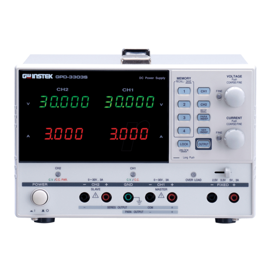
Page 16: Front Panel Overview
All manuals and user guides at all-guides.com GPD-X303S Series User Manual Front Panel Overview Channel CH1/CH3, CH2/ VoltMeter Ammeter Memory Keys Indicator CH4(Beep) Keys Voltage Knobs Parallel Keys Series Keys Current Knobs Output Key Lock Key CH4 Output CH2 Output GND Terminal CH1 Output CH3 Output... - Page 17 All manuals and user guides at all-guides.com OVERVIEW Control Panel Saves or recalls panel settings. Four Memory Keys settings, 1 ~ 4, are available. For save/recall details, see page41. GPD-2303S/2303S: Selects the output CH1/CH2 channel (CH1/CH2) for level adjustment. For level setting details, see page27.
- Page 18 All manuals and user guides at all-guides.com GPD-X303S Series User Manual Adjusts the output voltage level for Voltage Knobs the selected channel. Pressing the knob switches coarse and fine level setting. Adjusts the output current level for Current Knobs the selected channel. Pressing the knob switches coarse and fine level setting.
- Page 19 All manuals and user guides at all-guides.com OVERVIEW Terminals Default Terminals European Terminals Accepts a grounding wire. Terminal Indicates CH1 Constant CH1 CV/CC Voltage or Constant Current Indicator state. Outputs CH1 voltage and CH1 Output current. Indicates CH2 Constant Voltage, Constant Current, CV/CC/PAR Indicator or Tracking Parallel...
- Page 20 All manuals and user guides at all-guides.com GPD-X303S Series User Manual Indicates when CH3 (3303S) Overload output current is overloaded. Indicator Selects CH3 output voltage CH3 Voltage Selector for the GPD-3303S: 2.5V, 3.3V, or 5V. Indicates CH4 constant CH4 CV/CC Indicator voltage or constant current for the GPD-4303S.
-
Page 21: Rear Panel Overview
All manuals and user guides at all-guides.com OVERVIEW Rear Panel Overview Accepts a USB slave connector for USB Connector command-based remote control (page43). The power cord socket accepts the Power Cord / AC mains: 115V/230V, 50/60Hz. Fuse Socket For power up details, see page23. The fuse holder contains the AC main fuse. -
Page 22: Cv/Cc Crossover Characteristics
All manuals and user guides at all-guides.com GPD-X303S Series User Manual CV/CC Crossover Characteristics The GPD-4303S, GPD-3303S and GPD-3303S Background automatically switch between constant voltage mode (CV) and constant current mode (CC), according to load condition. When the current level is smaller than the output CV mode setting, the GPD-X303S series operates in Constant Voltage mode. -
Page 23: Setup
All manuals and user guides at all-guides.com SETUP ETUP This chapter describes how to properly power up and configure the GPD-X303S series before operation. Power Up Select AC voltage Before powering up the power supply, select the AC input voltage from the rear panel. Connect the AC power cord to Connect AC power cord... -
Page 24: Load Cable Connection
All manuals and user guides at all-guides.com GPD-X303S Series User Manual Load Cable Connection 1. Turn the terminal GTL-104A counterclockwise and loosen the screw. 2. Insert the cable terminal. 3. Turn the terminal clockwise and tighten the screw. Insert the plug into the socket. GTL-105A Insert the plug into the terminal. -
Page 25: Output On/Off
All manuals and user guides at all-guides.com SETUP Output On/Off Pressing the Output key turns Panel operation on all channel outputs. The key LED also turns on. Pressing the Output key again turns the output and the key LED off. Any of the following actions during output on Automatic output automatically turns it off. -
Page 26: Switch Between Channels
All manuals and user guides at all-guides.com GPD-X303S Series User Manual Switch between channels Switching between channels Panel operation only applies to GPD-4303S. Press the CH1/3 key to toggle between CH1 and CH3. The active channel will be shown on the channel indicator. -
Page 27: Operation
All manuals and user guides at all-guides.com OPERATION PERATION CH1/CH2 Independent Mode CH1 and CH2 outputs work independent of each Background / Connection other. 0 ~ 30V/0~3A for each channel Output rating 1. Make sure the PARA/ Panel operation INDEP and SER/INDEP keys are turned off (the key LEDs are off). - Page 28 All manuals and user guides at all-guides.com GPD-X303S Series User Manual Note: this diagram shows non-European terminals. 3. Set the CH1 output voltage (For CH1) and current. Press the CH1 key (LED turns on) and then use the Voltage and Current knob.
-
Page 29: Ch3 Independent Mode
All manuals and user guides at all-guides.com OPERATION CH3 Independent Mode For the GDP-3303S the CH3 rating is fixed at Background / 2.5V/3.3V/5V, 3A. CH3 for the 4303S is variable: Connection 0~5V,0~3A / 5.001~10V,0~1A . Output rating 3303S:2.5V/3.3V/5V,3A (fixed) 4303S:0~5V,0~3A / 5.001~10V,0~1A CH3 does not have tracking series/parallel mode. - Page 30 All manuals and user guides at all-guides.com GPD-X303S Series User Manual 2. 3303S: Select the output voltage, 2.5V/3.3V/5V using the CH3 voltage selector key. 4303S: Press the CH1/3 key to switch to CH3 (The CH3 indicator will light). Use the voltage and current knobs to set the voltage and current.
-
Page 31: Ch4 Independent Mode
All manuals and user guides at all-guides.com OPERATION CH4 Independent Mode The GPD-4303S has a rating of 5V/1A max. Background / Connection 5V/1A max Output rating CH4 does not have tracking series/parallel mode. No Tracking The CH4 output is not affected by CH1 and CH2 Series/Parallel modes. - Page 32 All manuals and user guides at all-guides.com GPD-X303S Series User Manual 3. To turn on the output, press the output key. The key LED turns on. CV → CC When the output value exceeds the set value, the C.V./C.C. indicator turns red. This indicates that CH3 has switched from constant voltage to constant current.
-
Page 33: Ch1/Ch2 Tracking Series Mode
All manuals and user guides at all-guides.com OPERATION CH1/CH2 Tracking Series Mode Tracking series operation doubles the Voltage Background capacity of the GPD-X303S series by internally connecting CH1 (Master) and CH2 (Slave) in series and combining the output to a single channel. CH1 (Master) controls the combined Voltage output level. - Page 34 All manuals and user guides at all-guides.com GPD-X303S Series User Manual Note: this diagram shows non-European terminals. 3. Press the CH2 key (LED turns on) and then use the Current knob to set the CH2 output current to the maximum level (3.0A). By default, the Voltage and Current knob work in the coarse mode.
- Page 35 All manuals and user guides at all-guides.com OPERATION Double the reading on the CH1 Voltage level Voltage meter. In the above case, the actual output is 20.0 x 2 = 40.0V. CH1 meter reading shows the Current level output Current. In the above case, 2.000A.
- Page 36 All manuals and user guides at all-guides.com GPD-X303S Series User Manual 1. Press the SER/INDEP key to activate the tracking series mode. The key LED turns 2. Connect the load to the front panel terminals, CH1+ & CH2−. Use the CH1 (−) terminal as the common line connection.
- Page 37 All manuals and user guides at all-guides.com OPERATION 5. To turn on the output (and LED), press the output key. 6. For the master (CH1) output level and CV/CC status, refer to the CH1 meter and indicator. CH1 meter reading shows the Master (CH1) voltage level output voltage.
- Page 38 All manuals and user guides at all-guides.com GPD-X303S Series User Manual The CH1 meter reading shows Slave (CH2) voltage level the output voltage. In the above case, 20.0V. The CH2 meter reading shows Slave (CH2) current level the output current. In the above case, 3.000A.
-
Page 39: Ch1/Ch2 Tracking Parallel Mode
All manuals and user guides at all-guides.com OPERATION CH1/CH2 Tracking Parallel Mode Tracking parallel operation doubles the current Background / capacity of the GPD-X303S series by internally Connection connecting CH1 and CH2 in parallel and combining the output to a single channel. CH1 controls the combined output. - Page 40 All manuals and user guides at all-guides.com GPD-X303S Series User Manual 3. To turn on the output, press the output key. The key LED turns on. 4. The CH2 C.V./C.C. PAR. indicator turns red, indicating tracking parallel (PARA) mode. 5. Press the CH1 key (LED turns on) and then use the Voltage and Current knob to set the output voltage...
-
Page 41: Save/Recall Setup
All manuals and user guides at all-guides.com SAVE/RECALL SETUP AVE/RECALL SETUP Save Setup The front panel settings can be stored into one of Background the four internal memories. The following list shows the setup contents. Contents Independent / tracking series / tracking parallel •... -
Page 42: Recall Setup
All manuals and user guides at all-guides.com GPD-X303S Series User Manual Recall Setup The front panel settings can be recalled from one of Background the four internal memories. The following list shows the setup contents. Contents Independent / tracking series / tracking parallel •... -
Page 43: Remote Control
Data flow control: None • Run this query command via the terminal Functionality application such as MTTTY (Multi-threaded TTY). check *IDN? This should return the identification information: Manufacturer, model name, serial number, firmware version. GW INSTEK, GPD-x303S, SN: xxxxxxxx, Vx.xx... -
Page 44: Remote Connection Step
All manuals and user guides at all-guides.com GPD-X303S Series User Manual Remote Connection Step Entering the 1. Connect the USB cable to the slave port. remote control mode 2. The connection will be automatically established, and the front panel shows a “USB…YES”... - Page 45 All manuals and user guides at all-guides.com REMOTE CONTROL 4. The power supply goes back to the local operation mode.
-
Page 46: Command Syntax
All manuals and user guides at all-guides.com GPD-X303S Series User Manual Command Syntax 1: command header Command format ISET<X>:<NR2>NL 2: output channel 3: separator 4: parameter 5: terminator(line feed) 1 (CH1) or 2 (CH2) Output channel Parameter Type Description Example boolean logic 0 (off), 1 (on) <Boolean>... -
Page 47: Command List
All manuals and user guides at all-guides.com REMOTE CONTROL The entered command is not allowed in the Command not allowed circumstance. Example: trying to set CH2 output while in the tracking mode. Undefined header The entered command does not exist, or the syntax is wrong. -
Page 48: Command Details
All manuals and user guides at all-guides.com GPD-X303S Series User Manual Command Details ISET<X>:<NR2> Sets the output current for the selected channel. Description 1= CH1, 2= CH2, (4303S: 3 = CH3, 4= CH4) Decimal number, range 0~3.200A <NR2> Minimum 10ms Response time Sets the CH1 output current to Example... - Page 49 All manuals and user guides at all-guides.com REMOTE CONTROL VSET<X>? Returns the output voltage setting. Description 1: CH1, 2: CH2, (4303S: 3: CH3, 4: CH4) Minimum 10ms Response time Returns the CH1 voltage setting Example VSET1? IOUT<X>? Returns the actual output current. Description 1: CH1, 2: CH2, (4303S: 3: CH3, 4: CH4) Minimum 10ms...
- Page 50 All manuals and user guides at all-guides.com GPD-X303S Series User Manual BEEP<Boolean> Turns the beep on or off. Description 0:off, 1:on <Boolean> Minimum 10ms Response time Turns on the beep Example BEEP1 OUT<Boolean> Turns on or off the output. Description 0: off, 1: on <Boolean>...
- Page 51 All manuals and user guides at all-guides.com REMOTE CONTROL Return parameter GW INSTEK,GPD-X3303,SN: xxxxxxxx, Vx.xx (Manufacturer, model name, serial number, firmware version) RCL<NR1> Recalls a panel setting. Description 1 – 4: Memory 1 to 4 <NR1> Minimum 10ms Response time...
- Page 52 All manuals and user guides at all-guides.com GPD-X303S Series User Manual Minimum 10ms Response time ERR? Checks the error status of the instrument and Description returns the last error message. Minimum 10ms Response time See page 46 for the list of error messages. Contents HELP? Shows the command list.
-
Page 53: Faq
All manuals and user guides at all-guides.com Q1. I pressed the panel lock key but the output still turns on/off. A1. For safety reasons the output key is not affected by the panel key lock feature. Q2. The CH3 overload indicator turned on – is this an error? A2. -
Page 54: Appendix
All manuals and user guides at all-guides.com GPD-X303S Series User Manual PPENDIX Fuse Replacement 1. Take off the power cord and remove the fuse Steps socket using a minus driver. 2. Replace the fuse in the holder. 100V/120V:T6.3A/250V Rating • 220V/230V:T3.15A/250V •... -
Page 55: Specifications
All manuals and user guides at all-guides.com APPENDIX Specifications The specifications apply when the GPD-X303S series are powered on for at least 30 minutes under +20°C – +30°C. Output Ratings CH1/CH2 0 ~ 30V / 0 ~ 3A Independent CH1/CH2 0 ~ 60V / 0 ~ 3A Series CH1/CH2... - Page 56 All manuals and user guides at all-guides.com GPD-X303S Series User Manual Voltmeter 32V full scale, 5 digits 0.4" LED display Program Voltage: ± (0.03% of reading + 10mV) Accuracy Current: ± (0.3% of reading + 10mA) Read back Voltage: ± (0.03% of reading + 10mV) Accuracy Current: ±...
-
Page 57: Declaration Of Conformity
All manuals and user guides at all-guides.com APPENDIX Declaration of Conformity GOOD WILL INSTRUMENT CO., LTD. (1) No.7-1, Zhongxing Rd., Tucheng Dist., xinbei City 236, Taiwan (2) No. 69, Lu San Road, Suzhou City (Xin Qu), Jiangsu Sheng, China declare, that the below mentioned product Type of Product: Power Supply Model Number: GPD-2303S/ GPD-3303S / GPD-4303S are herewith confirmed to comply with the requirements set out in the... - Page 58 All manuals and user guides at all-guides.com GPD-X303S Series User Manual NDEX Automatic out off ....25 Operation......7 Banana plug ......24 Specification ..... 55 Storage......... 8 Baud rate Error messages, remote Remote control....51 Beep setting control ......46, 52 Contents......25 Front panel Manual.......25 Lock (manual) ....
-
Page 59: Index
All manuals and user guides at all-guides.com INDEX FAQ ........53 Command syntax..... 46 manual .......25 Connection test....43 Remote .......50 Error messages ....46 Interface......43 Output voltage setting Manual .......28 Save settings Remote control....48 Manual ......41 Over load indicator ....30 Remote.......
Need help?
Do you have a question about the GPD-303S Series and is the answer not in the manual?
Questions and answers