Advertisement
Available languages
Available languages
Quick Links
TQG 641/HA(WH)
Italiano
Istruzioni per l'uso
PIANO
Sommario
Istruzioni per l'uso,1
Avvertenze,3
Assistenza,8
Descrizione dell'apparecchio,10
Installazione,12
English
Operating Instructions
HOB
Contents
Operating Instructions,1
Warnings,3
Assistance,8
Description of the appliance,10
Mode d'emploi
TABLE DE CUISSON
Sommaire
Mode d'emploi,1
Avertissements,4
Assistance,8
Description de l'appareil,10
Español
Manual de instrucciones
ENCIMERA
Sumario
Manual de instrucciones,1
Advertencias,4
Asistencia,8
Descripción del aparato,10
Portuges
Instruções para a utilização
Índice
Instruções para a utilização,1
Advertências,5
Assistência,9
Descrição do aparelho,11
Instalação,40
Français
Advertisement
Chapters

Related Manuals for Hotpoint Ariston TQG 641/HAWH


Summary of Contents for Hotpoint Ariston TQG 641/HAWH
-
Page 1: Table Of Contents
TQG 641/HA(WH) Français Mode d’emploi TABLE DE CUISSON Sommaire Mode d’emploi,1 Avertissements,4 Assistance,8 Description de l’appareil,10 Installation,26 Mise en marche et utilisation,30 Précautions et conseils,30 Nettoyage et entretien,31 Anomalies et remèdes,31 Italiano Español Istruzioni per l’uso Manual de instrucciones PIANO ENCIMERA Sommario Sumario... - Page 2 Deutsch Bedienungsanleitung KOCHMULDE Inhaltsverzeichnis Bedienungsanleitung,2 Hinweise,5 Kundendienst,9 Beschreibung Ihres Gerätes,11 Installation,47 Inbetriebsetzung und Gebrauch,51 Vorsichtsmaßregeln und Hinweise,51 Reinigung und Pflege,52 Störungen und Abhilfe,52 Nederlands Gebruiksaanwijzing KOOKPLAAT Inhoud Gebruiksaanwijzing,2 Belangrijk,6 Service,9 Beschrijving van het apparaat,11 Het installeren,54 Starten en gebruik,58 Voorzorgsmaatregelen en advies,58 Onderhoud en verzorging,59 Storingen en oplossingen,59 Українська...
- Page 3 ATTENZIONE: In caso di danneggiamento del piano in vetro: - spegnere immediatamente tutti i bruciatori e Avvertenze eventuali elementi riscaldanti elettrici e scollegare l’apparecchio dalla rete elettrica ATTENZIONE: Questo apparecchio e le sue parti - non toccare la superfice dell’apparecchio. accessibili diventano molto caldi durante l’uso.
- Page 4 CAUTION: In case of hotplate glass breakage: Cet appareil ne peut pas être allumé au moyen - shut immediately off all burners and any electrical d’un temporisateur extérieur ou d’un système de heating element and isolate the appliance from the commande à...
- Page 5 cuando los quemadores o la placa eléctrica todavía Nunca utilize equipamento de limpeza a vapor ou están calientes. de alta pressão para limpar o aparelho. El aparato no se debe poner en funcionamiento a Elimine os líquidos presentes na tampa antes de través de un temporizador externo o de un sistema abri-la.
- Page 6 Sie das Gerät aus und ersticken Sie die Flamme mit mogen niet door kinderen worden uitgevoerd, tenzij einem Deckel oder einer feuerfesten Decke. onder toezicht. ZUR BEACHTUNG: Brandgefahr: Keine PAS OP: Het kan gevaarlijk zijn een fornuis met vet Gegenstände auf den Kochstellen liegen lassen. of olie onbewaakt te laten.
- Page 7 користування цим приладом дітьми віком від 8 років, а також особами з обмеженими фізичними, сенсорними або розумовими можливостями або особами без належного досвіду і знань, якщо вони перебувають під постійним контролем або проінструктовані щодо правил з небезпечного користування приладу і усвідомлюють ступені ризику.
- Page 8 Assistenza Assistance Comunicare: Communicating: • il tipo di anomalia • the type of problem encountered. • il modello della macchina (Mod.) • appliance model (Mod.) • il numero di serie (S/N) • serial number (S/N) Queste ultime informazioni si trovano sulla targhetta caratteristiche posta This information is found on the data plate located on the appliance and/or sull’apparecchio.
- Page 9 Assistência Comunique: • o tipo de avaria • o modelo da máquina (Mod.) • o número de série (S/N) Estas últimas informações encontram-se na placa de identificação situada no aparelho e/ou na embalagem. Kundendienst Geben Sie bitte Folgendes an: • die genaue Beschreibung des Fehlers •...
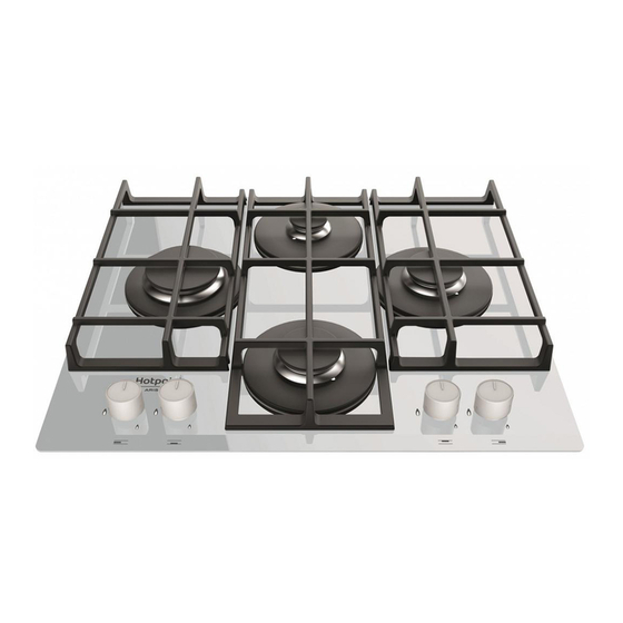
- Page 10 Descrizione dell’apparecchio Description de l’appareil Vista d’insieme Vue d’ensemble 1. Griglie di appoggio per RECIPIENTI DI COTTURA 1. Grilles support de CASSEROLES 2. BRUCIATORI GAS 2. BRÛLEURS À GAZ 3. Manopole di comando dei BRUCIATORI GAS 3. Manettes de commande des BRÛLEURS GAZ 4.
- Page 11 Descrição do aparelho Beschrijving van het apparaat Vista de conjunto Algemeen aanzicht 1. Grades de suporte para RECIPIENTES DE COZEDURA 1. Roosters voor PANNEN 2. QUEIMADORES A GÁS 2. GASBRANDERS 3. Selectores de comando dos QUEIMADORES A GÁS 3. Knoppen voor het regelen van de GASBRANDERS 4.
- Page 12 Installazione il bidone in utilizzo, collocato in modo da non essere soggetto all’azione diretta di sorgenti di calore (forni, camini, stufe, ecc.) capaci di portarlo a temperature superiori ai 50°C. ! È importante conservare questo libretto per poterlo consultare in ogni momento.
- Page 13 ! Usare i ganci contenuti nella “confezione accessori” ! Il cavo deve essere controllato periodicamente e sostituito solo da tecnici autorizzati (vedi Assistenza). • Nel caso in cui il piano non sia installato su di un forno incasso, è ! L’azienda declina ogni responsabilità qualora queste norme non vengano necessario inserire un pannello di legno come isolamento.
- Page 14 • Regolazione minimi 1. Portare il rubinetto sulla posizione di minimo; 2. Togliere la manopola ed agire sulla vite di regolazione posta all’interno o di fianco all’astina del rubinetto fino ad ottenere una piccola fiamma regolare. 3. Verificare che ruotando rapidamente la manopola dalla posizione di massimo a quella di minimo non si abbiano spegnimenti dei bruciatori.
- Page 15 Tabella caratteristiche bruciatori e ugelli Tabella 1 Gas Liquido Gas Naturale Bruciatore Diametro Potenza termica By-pass Ugello Portata* Ugello Portata* (mm) kW (p.c.s.*) 1/100 1/100 1/100 (mm) (mm) (mm) Nomin. Ridot. Rapido (R) 3.00 0.70 116(Y) Semi Rapido (S) 1.65 0.40 96(Z) Ausiliario (A)
-
Page 16: Avvio E Utilizzo,16
Avvio e utilizzo Precauzioni e consigli ! Su ciascuna manopola è indicata la posizione del bruciatore gas ! L’apparecchio è stato progettato e costruito in conformità alle norme corrispondente. internazionali di sicurezza. Queste avvertenze sono fornite per ragioni di sicurezza e devono essere Bruciatori gas lette attentamente. -
Page 17: Manutenzione E Cura,17
Manutenzione rubinetti gas essere consegnati gratuitamente ai negozianti anche se non si acquista nulla (solo nei negozi con superficie di vendita superiore a 400 mq). Per Con il tempo può verificarsi il caso di un rubinetto che si blocchi o presenti ulteriori informazioni sulla corretta dismissione degli elettrodomestici i difficoltà... - Page 18 ATTENZIONE...
-
Page 19: Installation,19
Installation Fitting the appliance The following precautions must be taken when installing the hob: • kitchen cabinets adjacent to the appliance and taller than the top of the ! Before operating your new appliance please read this instruction booklet hob must be at least 200 mm from the edge of the hob. carefully. - Page 20 Gas connection • Where the hob is not installed over a built-in oven, a wooden panel must be installed as insulation. This must be placed at a minimum distance of The appliance should be connected to the main gas supply or to a gas 20 mm from the lower part of the hob.
- Page 21 5. Once the adjustment has been made, replace the seals on the by-passes using sealing wax or a similar substance. ! If the appliance is connected to liquid gas, the regulation screw must be fastened as tightly as possible. ! Once this procedure is finished, replace the old rating sticker with one indicating the new type of gas used.
- Page 22 Burner and nozzle specifications Table 1 Liquid Gas Natural Gas Burner Diameter Thermal Power By-pass Nozzle Flow* Nozzle Flow* (mm) kW (p.c.s.*) 1/100 1/100 1/100 (mm) (mm) (mm) Nomin. Reduc. 0.70 116(Y) Rapid (R) 3.00 0.40 96(Z) Semi Rapid (S) 1.65 0.40 79(6)
-
Page 23: Start-Up And Use,23
Start-up and use Precautions and tips ! The position of the corresponding gas burner is shown on every knob. ! This appliance has been designed and manufactured in compliance with international safety standards. The following warnings are provided for safety Gas burners reasons and must be read carefully. -
Page 24: Maintenance And Care,24
Troubleshooting Respecting and conserving the environment • Cook your food in closed pots or pans with well-fitting lids and use as little water as possible. Cooking with the lid off will greatly increase energy It may happen that the appliance does not function properly or at all. Before consumption. - Page 25 NOTICE...
-
Page 26: Installation,26
Installation ou une aération plus efficace, en augmentant la puissance d’aspiration mécanique si déjà prédisposée. • (Pour la France et la Belgique) Les gaz de pétrole liquéfiés, plus ! Conservez ce mode d’emploi pour pouvoir le consulter à tout moment. lourds que l’air, se déposent et stagnent vers le bas. - Page 27 Devant • la prise est bien compatible avec la fiche de l’appareil. Si ce n’est pas le cas, remplacez la prise ou la fiche, n’utilisez ni rallonges ni prises multiples. ! Après installation de l’appareil, le câble électrique et la prise de courant doivent être facilement accessibles ! Le câble ne doit être ni plié...
- Page 28 Vérification de l’étanchéité PLAQUETTE SIGNALETIQUE ! Une fois l’installation terminée, vérifier l’étanchéité de tous les raccords en Raccordements utilisant une solution savonneuse et jamais une flamme. voir plaquette signalétique électriques Adaptation aux différents types de gaz (pour la France et la Belgique) Cet appareil est conforme aux Directives Pour adapter la table à...
- Page 29 Caractéristiques des brûleurs et des injecteurs Tableau 1 (Pour la France et la Belgique) Gaz Liquidés Gaz Naturel Brûleur Diamètre Puissance By-pass Injecteur Débit* Injecteur Débit* Puissance Débit* thermique thermique (mm) 1/100 1/100 1/100 kW (p.c.s.*) kW (p.c.s.*) (mm) (mm) (mm) Nominal Réduit...
-
Page 30: Mise En Marche Et Utilisation,30
Mise en marche et utilisation Précautions et conseils ! Cet appareil a été conçu et fabriqué conformément aux normes ! La position du brûleur gaz correspondante est indiquée sur chaque manette. internationales de sécurité. Ces conseils sont fournis pour des raisons de sécurité... -
Page 31: Nettoyage Et Entretien,31
! Pour ne pas endommager le dispositif d’allumage électrique, actionnez- la ‘‘poubelle barrée’’ est apposée sur tous les produits pour rappeler les obligations de collecte séparée. Les consommateurs devront contacter le uniquement lorsque les brûleurs ont été remis en place. les autorités locales ou leur revendeur concernant la démarche à... - Page 32 ATTENTION...
-
Page 33: Instalación,33
Instalación o depositadas en ambientes o espacios a un nivel más bajo del suelo (sótanos, etc.) Es conveniente conservar en el ambiente sólo la botella que se está utilizando, colocada de modo que no quede expuesta a la acción ! Es importante conservar este manual para poder consultarlo en todo directa de fuentes de calor (hornos, chimeneas, estufas, etc.) capaces de momento. - Page 34 Adelante • la tensión de alimentación eléctrica esté comprendida dentro de los valores indicados en la placa de características; • la toma sea compatible con el enchufe del aparato. Si no es así, sustituya la toma o el enchufe; no utilice prolongaciones ni conexiones múltiples. ! Una vez instalado el aparato, el cable eléctrico y la toma de corriente deben ser fácilmente accesibles.
- Page 35 3. Vuelva a colocar las piezas realizando las operaciones en sentido PLACA DE CARACTERÍSTICAS contrario. Conexiones 4. Al finalizar la operación, sustituya la anterior etiqueta de calibrado con la ver placa de características eléctricas correspondiente al nuevo gas que se va a utilizar, disponible en nuestros Centros de Asistencia Técnica.
- Page 36 Características de los quemadores e inyectores Tabla 1 Gas Liquido Gas Natural Quemador Diametro Potencia térmica By-pass Pico Capacidad* Pico Capacidad* (mm) kW (p.c.s.*) 1/100 1/100 1/100 (mm) (mm) (mm) Nomin. Riduc. Ràpido (R) 3.00 0.70 116(Y) Semi Ràpido (S) 1.65 0.40 96(Z)
-
Page 37: Puesta En Funcionamiento Y Uso,37
Puesta en funcionamiento y uso Precauciones y consejos ! En cada mando está indicada la posición del quemador a gas ! El aparato ha sido proyectado y fabricado en conformidad con las normas correspondiente. internacionales de seguridad. Estas advertencias se suministran por razones de seguridad y deben ser Quemadores a gas leídas atentamente. -
Page 38: Mantenimiento Y Cuidados,38
Ahorrar y respetar el medioambiente Mantenimiento de las llaves de gas • Cocine los alimentos en ollas o sartenes cerrados con tapas que ajusten Con el tiempo puede suceder que una llave se bloquee o presente dificultad bien y usen la menor cantidad de agua posible. Cocinar sin la tapa, para girar, en esos casos será... - Page 39 ATENCIÓN...
-
Page 40: Plano
Instalação mesmo vazios ou parcialmente cheios, não devem ser instalados nem guardados em lugares ou vãos a nível mais baixo do que o solo (caves etc.). É oportuno deixar na cozinha apenas o cilindro sendo utilizado, ! É importante guardar este folheto para poder consultá-lo a qualquer colocado de maneira a não ser sujeito à... - Page 41 Frente • a tomada tenha a capacidade de suportar a carga máxima de potência da máquina, indicada na placa de identificação; • a tensão de alimentação seja entre os valores da placa de identificação; • a tomada seja compatível com a ficha do aparelho. Em caso contrário, substitua a tomada ou a ficha;...
- Page 42 1. Tire as grades do plano e solte os queimadores do lugar. PLACA DAS CARACTERÍSTICAS 2. Desparafusar os bicos utilizando uma chave a tubo de 7mm, e substituí- Ligações los com aqueles apropriados para o novo tipo de gás (ver tabela 1 ver quadro das características eléctricas “Características dos queimadores e dos bicos”).
- Page 43 Características dos queimadores e bicos Tabla 1 Gás Liquefeito Gás Natural Bruciatore Diâmetro Poténcia térmica By-pass Bico Capacidad* Bico Capacidad* (mm) kW (p.c.s.*) 1/100 1/100 1/100 (mm) (mm) (mm) Nomin. Ridot. Ràpido (R) 3.00 0.70 116(Y) 0.40 96(Z) Semi Rápido (S) 1.65 0.40 79(6)
-
Page 44: Início E Utilização,44
Início e utilização Precauções e conselhos ! Em cada selector está indicada a posição do queimador de gás o ! Este aparelho foi projectado e fabricado em conformidade com as normas correspondente. internacionais de segurança. Estas advertências são fornecidas por razões de segurança e devem ser lidas com atenção. -
Page 45: Manutenção E Cuidados,45
Manutenção das torneiras do gás Os consumidores devem contactar as autoridades locais ou os pontos de venda para solicitar informação referente ao local apropriado onde devem Com o tempo pode ocorrer o caso de uma torneira que se bloqueie ou depositar os electrodomésticos velhos. - Page 46 ATENÇÃO...
- Page 47 Installation • Die Flüssiggase, die schwerer als Luft sind, stauen sich im unteren Raumbereich. Räume, in denen Gasflaschen mit GPL-Flüssiggas gelagert werden, müssen demnach in Bodenhöhe mit geeigneten ! Bewahren Sie diese Bedienungsanleitung bitte sorgfältig auf, damit Sie sie Abzugsöffnungen ins Freie ausgestattet werden, damit das Gas im jederzeit zu Rate ziehen können.
- Page 48 Haken-Befestigungsschema Vorschriften entsprechender Schalter mit einer Mindestöffnung der Kontakte von 3 mm zwischenzuschalten. (Der Erdleiter darf vom Schalter nicht unterbrochen werden.) Das Versorgungskabel muss so verlegt werden, dass es an keiner Stelle einer Temperatur ausgesetzt wird, die 50°C über der Raumtemperatur liegt. ! Der Installateur ist für den ordnungsgemäßen elektrischen Anschluss sowie die Einhaltung der Sicherheitsvorschriften verantwortlich.
- Page 49 ! Sollte der Gasdruck der Anlage von den vorgesehenen Werten abweichen, Anschluss mittels Inox-Schläuchen mit hermetischen Wänden Bei dem Anschlussstück für den Gaseingang handelt es sich um einen oder nicht konstant sein, muss das Zuleitungsrohr mit einem geeigneten zylindrischen 1/2 Gas-Gewindezapfen. Druckregler (gemäß...
- Page 50 Merkmale der Brenner und Düsen Tabelle 1 Flüssiggas Erdgas Brenner Durch- Wärmeleistung By-pass Düse Menge* Düse Menge* Wärme- Menge* messer leistung kW (p.c.s.*) 1/100 1/100 1/100 kW (p.c.s.*) (mm) (mm) (mm) (mm) Nominal Reduz. Butan Propan 0.70 116(Y) Starkbrenner (R) 3.00 3.00 Mittelstarker Brenner (S)
- Page 51 Inbetriebsetzung und Gebrauch Die veränderliche Stabilität eines Topfs ist meist vom Topf selbst abhängig (bzw. davon, wie er während des Gebrauchs ! Auf jedem Reglerknopf ist gekennzeichnet, welcher Gasflamme oder aufgestellt wird). In einwandfreiem Elektroplatte* er entspricht. Gleichgewicht zentral über dem Brenner stehende Töpfe mit flachem Boden und mit Gasbrenner einer der Leisten des Gitters gefluchteten...
- Page 52 • Kinder dürfen nicht mit dem Gerät spielen. • Reinigen Sie diese von Hand mit warmem Wasser und einem • Dieses Gerät kann nicht mit einem externen Timer oder einem nicht scheuernden Reinigungsmittel. Entfernen Sie dabei jegliche getrennten Fernsteuerungssystem betrieben werden. Lebensmittelreste und prüfen Sie, ob Brenneröffnungen verstopft sind.
- Page 53 ZUR BEACHTUNG...
- Page 54 Het installeren LPG-flessen mogen dus niet worden geïnstalleerd of bewaard in vertrekken die lager liggen dan de vloer (kelders, enz.). Het is beter alleen de in gebruik zijnde fles in het vertrek te bewaren, zodanig geplaatst dat ! Bewaar dit boekje zorgvuldig voor eventuele verdere raadpleging. Wanneer hij niet in rechtstreeks contact staat met warmtebronnen (oven, open u het product weggeeft, verkoopt, of wanneer u verhuist, dient u dit boekje haard, kachel, enz.) die hem tot temperaturen van meer dan 50°C zouden...
- Page 55 Voor • de spanning zich bevindt tussen de waarden die staan aangegeven op het typeplaatje; • het stopcontact en de stekker overeenkomen. Als dat niet zo is, dient u ofwel de stekker ofwel het stopcontact te vervangen; gebruik geen verlengsnoeren of dubbelstekkers. ! Wanneer het apparaat geïnstalleerd is moeten het snoer en het stopcontact gemakkelijk te bereiken zijn.
- Page 56 Controleren gasdichtheid TYPEPLAATJE ! Nadat het installeren heeft plaats gevonden moet de perfecte gasdichtheid Elektrische van alle verbindingsstukken worden gecontroleerd met een zeepoplossing zie typeplaatje aansluitingen en nooit met een vlam. Dit apparaat voldoet aan de volgende EU Richtlijnen: Aanpassen aan de verschillende soorten gas (voor België) - 2006/95/EG van 12/12/06 (Laagspanning) Voor het aanpassen van de kookplaat aan een ander soort gas dan waarvoor en daaropvolgende wijzigingen...
- Page 57 Kenmerken van de branders en de straalpijpjes Table 1 (Voor Belgie) Vloeibaar gas Aardgas Gaspit Doorsnee Thermisch By-pass Straal. Bereik* Straal. Bereik* Thermisch Bereik* vermogen vermogen (mm) 1/100 1/100 1/100 kW (p.c.s.*) kW (p.c.s.*) (mm) (mm) (mm) Nominaal Gereduc. Butane Propane Snel (R) 0.70...
-
Page 58: Snel (R)
Starten en gebruik Voorzorgsmaatregelen en advies ! Op iedere knop staat aangegeven waar de gasbrander of de elektrische Dit apparaat is ontworpen en vervaardigd volgens de geldende internationale plaat* zich precies bevindt. veiligheidsvoorschriften. Deze aanwijzingen zijn geschreven voor uw veiligheid en u dient ze derhalve goed door te nemen. - Page 59 Energiebesparing en milieubehoud Onderhoud gaskranen • Gebruik de residuele warmte van uw ovenplaat optimaal door de gietijzeren Met verloop van tijd kan een kraan stroef worden of vast blijven zitten; in dat platen 10 minuten en keramiek ovenplaten 5 minuten voor het einde van geval is het noodzakelijk hem te vervangen.
- Page 60 PAS OP...
- Page 61 Установка газ у разі витоку. Внаслідок цього балони, які містять зріджений газ, частково чи повністю заповнені, не повинні бути встановлені або зберігатися у приміщеннях або сховищах, які знаходяться ! Перед початком експлуатації Вашої нової плити, будь ласка, прочитайте нижче рівня землі (підвали тощо). Балон, який використовується і уважно...
- Page 62 Передня сторона • напруга знаходиться в межах значень, вказаних на табличці даних. • розетка сумісна з вилкою приладу. Якщо розетка не сумісна з вилкою, попросіть фахівця замінити її. не використовуйте подовжувачі або декілька розеток. ! Кабель живлення і розетки повинні бути легко доступні, після встановлення...
- Page 63 3. Знову зберіть частини, виконуючи описану процедуру в зворотному порядку. 4. По завершенні процедури, замініть стару етикетку з даними про тип газу новою з відповідною новою інформацією. Такі етикетки можна отримати в будь-якому нашому сервісному центрі. • Налаштування первинного повітря конфорки Не...
-
Page 64: 214 116(Y) 286
Ха а а а а Та З а П а Т а Ф а В а * Ф а В а * Па Д а By-pass 1/100 1/100 1/100 В (p.c.s.*) Н i . З 116(Y) Ш а 3.00 0.70 96(Z) На... - Page 65 Ввімкнення і використання Запобіжні заходи та поради ! Положення відповідних газових пальників показано на кожній ! Ця плита була розроблена і виготовлена відповідно до міжнародних ручціуправління. стандартів безпеки. З метою Вашої безпеки повинні бути ретельно прочитані наступні попередження. Газові пальники Загальні...
- Page 66 Обслуговування газового крану на приладі нагадує Вам про Ваші зобов’язання, щодо його окремної утилізації. Споживачі повинні звернутися до місцевих органів або З часом, кран може застрягти або важко повертатися. Якщо це продавця для отримання інформації проправильну утилізацію свого станеться, кран необхідно замінити. старого...
- Page 67 УВАГА! І К а С А - а І І а , 60044 Фа а ТОВ "І У а а" 47, В а А а М 01001, К . М...
- Page 68 195142358.00 02/2016 - XEROX FABRIANO Indesit Company S.p.A. Viale Aristide Merloni,47 60044 Fabriano (AN) www.hotpoint.eu...
Need help?
Do you have a question about the TQG 641/HAWH and is the answer not in the manual?
Questions and answers