Table of Contents

Related Manuals for Kanomax TABmaster 6720


Summary of Contents for Kanomax TABmaster 6720
- Page 1 TABmaster Model 6720 Instruction Manual Be sure to read this manual thoroughly before using the instrument. Fully understand and pay attention to each caution mentioned. Please keep this manual for ready reference. 01003 22.01...
- Page 2 Attention: In order to ensure your interests and enable you to receive timely and effective after-sales service, please fill in the "Warranty Card" carefully and cut it along the dotted line. After copying, fax or mail it to our company according to our company's contact information.
-
Page 3: Table Of Contents
CONTENTS Composition & Parts ............................3 Attentions & Notes ............................5 1. Introduction..............................8 1.1 Product Features ..........................8 1.2 Main Specificaion ..........................8 2. Capture Hood Structure..........................9 2.1 Instrument Base ..........................9 2.2 Micromanometer ..........................10 3.Installation ..............................10 3.1 Capture Hood Installation ....................... - Page 4 5.2.1 Date&Time Setting ....................... 17 5.2.2 Standard/Actual Test ......................18 5.2.3 Bluetooth Setting ........................18 5.2.4 Printer Connecting........................ 18 5.2.5 Compensation K factor ......................19 5.2.6 Input Current Temperature ....................19 5.3 Data Handling ..........................19 5.3.1 Scanning ..........................19 5.3.2 Delete ............................
-
Page 5: Composition & Parts
Composition & Parts ⚫ Capture Hood 6720 Standard components: Items Qty. Micro-manometer Model 6720-DP Instrument base Fabric Hood: 610× 610 mm Carrying case Portable handle Frame Poles Back pressure plate Communication cable AA batteries Calibration certificate CD-Rom(Manual and software inside) Quick-Guide ⚫... - Page 6 6720-DP Standard: Items Qty. Micro-manometer Model6720-DP Velocity Grid Carrying case Pressure tubing Communication cable AA batteries Calibration certificate CD-Rom(Manual and software inside) Quick-Guide 6720-DP Optional Parts: Items Specifications 2.3*200mm 4*300mm Pitot Tube 8*500mm Bluetooth printer main unit Printer paper: 57mm*φ30mm AC adapter DC5V...
-
Page 7: Attentions&Notes
… Otherwise, it may cause an electric shock, fire or damage the sensor. Using properly ○ During use, if the instrument emits abnormal smell, sound, smoke or liquid flows into the instrument, please unplug the AC adapter and remove the battery immediately, and send it to the KANOMAX maintenance department for repair. - Page 8 … Otherwise, there is possibility of electric shock, fire or instrument Using properly malfunction. ○ Do not exposure the instrument to rain or water. … Otherwise, it may cause a fire or a explosion. Forbidden CAUTION ○ Always unplug the instrument when it is not in use. …...
-
Page 10: Introduction
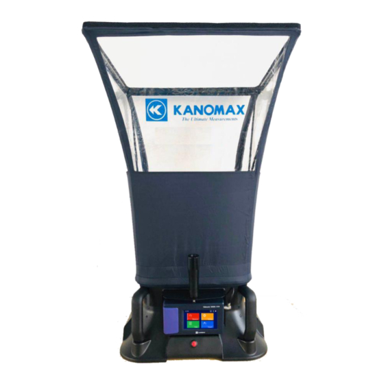
1. Introduction TAB master Model 6720 is a kind of intelligent test instrument with multifunctional of air flow test, velocity test and micro-differential pressure test. It’s widely used in air flow testing of air-conditioning, HVAC system and other places, especially for the high precision micro-differential pressure test. 1.1 Product Features ◆... -
Page 11: Capture Hood Structure
4 pcs of 5No.-model batteries (about 14hrs available)or DC5V Power Source adapter Weight Approx.3.6kg 2.Capture Hood Structure Frame Poles Pivot window Hood Base Micro-man ometer 2.1 Instrument Base 1.The exterior structure of the base Portable handle Micro-manomete ON/OFF button 2.The internal structure of the base 3. -
Page 12: Micromanometer
2.2 Micromanometer Structure Display LCD Airport(-) Airport(+) Base connector Adapter connector Power on/off Back Front view Side view Battery Compartment Portable handle connector Mini USB interface Bottom view Top view 3. Installation 3.1. Capture Hood Installation 1.Installations of fabric hood and base Note:... -
Page 13: Velocity Grid Installation
Note: The poles always cross in an “X” shape when assembling. To remove the poles, simply reverse the step 3.Installations of micro-manometer and portable handle ② ③ ① Note:1)Release the poles and portable handle when packing in the carring case to avoid case damaged. 2)The micromanometer number corresponds to the base number one by one 3.2 Velocity Grid Installation Air velocity testing can be achieved when micromanometer works together with the velocity Grid. -
Page 14: Operation Directions
(-) (+) 4. Operation Directions 4.1. Power Supply 1.Power by AC adapter.AC adapter will be as the priority power supply when the AC adapter and batteries are capable of using. The specification of the AC adapter is: I/P:AC 110-240V 50/60HZ O/P:DC 5V/2A。... -
Page 15: On/Off
3) It is recommended you change batteries when the power shows low. 4.2 ON/OFF POWER 1. Getting Started Press 【 POWER】 for two seconds, and the instrument will turn on,displaying “KANOMAX” then enter into the testing interface. 2. Shut Down Press【POWER】for two seconds, and the instrument will turn off automatically. -
Page 16: Testing System
1.Measure/Test System--According to tools, the corresponding test values. 2.Setting/Instrument Settings—Date &Time, Bluetooth Switch, printer connecting, etc. 3.Data/Data Handling--Display storage data. The functions of print and delete are available. 4.Export/Data Output--Export stored data via PC. 5.1. Measuring System 1. Temperature, Humidity(Capture Hood)2.Test Data Display 3.Atmospheric Pressure 4. -
Page 17: Back Pressure Measurement Mode
START …... 1) After testing start for about 8s with stably measuring , output displaying the test data for the first time. 2) Go on the testing with frequency of 1s for data updating. 3) The continuously outputting is as the average data and be related with the “Damp Per.”set by user. More larger of the value of ”Damp Per.”... -
Page 18: Print Settings
Note: 1) After testing start for about 8s, indicating “Open Flap”It’s time for switching on the Back Pressure Plate as needed. 2) Press START for about 8s, testing stop, real airflow outputting with back pressure compensation. 3) When select Velocity Grid、 Pitot tube、 Micromanometer for testing, Back Pressure Compensation will be not available. -
Page 19: Id Setting
5.1.7 Test ID Setting (1)The maximum number of Test IDs is 20. (2)Every tool owns independent test ID. (3) A Test ID can contain up to 100 Cycles. 5.1.8 Units Setting (1)Testing area is touchable. (2)All tools are without same unit. -
Page 20: Standard/Actual Test
5.2.2 Standard/Actual Test Note: 1) STD is ON, means Standard (Std) environmental test. The atmospheric pressure is 101.32kPa and the temperature is 21.1° C. 2) STD is OFF, means Actual (Act) environmental test, including atmospheric pressure compensation and temperature compensation. 3)... -
Page 21: Compensation K Factor
Note: 1) Please connect to our dedicated portable Bluetooth printer, the printer's Mac address is marked in the battery box. 2) Please try to keep the distance between the Bluetooth printer and the air volume cover as close as possible to keep the print data from being lost. -
Page 22: Delete
5.3.2 Delete 1)Delete ID 2)Delete cycle Note: 1) Only the data under the current tool is allowed to be deleted. 2) Once the data is deleted, it cannot be recovered. 3) Please delete invalid data in time to ensure effective storage space. 5.3.3 Print 1)ID Method 2)Cycle Method... -
Page 23: Data Output
3)Disconnect the printer 5.4 Data Output Note: 1) The export function is to transfer the saved test data to the computer. It needs to be used together with the communication cable and data acquisition software provided by our company. Please refer to the "6720 Data Acquisition Software Instruction Manual". -
Page 24: Common Trouble Shooting
6. Common Trouble Shooting Please check the following list before requesting a repair: Symptom Possible Causes Trouble Shooting Incorrect specification of the AC Check and refer to Chapter4.1 Adapter in Manual No display when power On Check and refer to Chapter4.1 Battery installation error in Manual Low or dead battery power... -
Page 25: Warranty And After Service
7.Warranty and After Service 7.1 Warranty ◆ The product comes with an instrument warranty card. When you purchase the product, please be sure to fill in the required information in the warranty card accurately and send it back to our company at the address listed in time. - Page 27 #1314-1315, Zhongliang Square, 56-39 Yellow River North Street, HuangGu District, Shenyang City. PRC. TEL: 86-024-23846440 83951688 83951788 FAX:86-024-23898417-820 URL: www.kanomax.com.cn □ Kanomax Group Companies KANOMAX USA,INC. 219U.S. Highway 206,Andover, New Jersey 07821 Tel: 1-800-247-8887(USA) / 1-973-786-6386 FAX:1-973-786-7586 www.kanomax-usa.com/ URL: E-mail: info@kanomax-usa.com □...
Need help?
Do you have a question about the TABmaster 6720 and is the answer not in the manual?
Questions and answers