Advertisement
Quick Links
Installation Guide
Pressure Monitoring
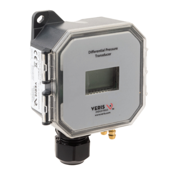
Differential Pressure / Air Velocity Transducer
Product Overview
PX3
The PX3 transducer can measure either air pressure or velocity with the flip of a switch.
The PX3 is available in three installation configurations: duct, panel or universal. Duct and
50
panel models have two pressure and velocity ranges: 0-1 in. WC / 0-3,000 ft/min or
1-10 in. WC / 3,000-6,000 ft/min with four field-selectable sub-ranges. The universal
WARNING
model comes in one pressure/velocity range: 0-10 in. WC / 0-7,000 ft/min with seven
HAZARD OF ELECTRIC
field-selectable sub-ranges for pressure and eight for velocity. All variants are available
SHOCK, EXPLOSION
with and without display. The PX3 has an IP65/NEMA 4 environmental rating and a 5-year
OR ARC FLASH
limited warranty.
• Apply appropriate personal protective
equipment (PPE) and follow safe electrical
work practices. See NFPA 70E or CSA Z462.
Product Identification
• This equipment must only be installed
and serviced by quali ed electrical
Enclosure
personnel.
• Turn o all power supplying this
PX3
equipment before working on or inside
D = Duct
equipment.
P = Panel
• Always use a properly rated voltage
sensing device to con rm power is o .
• Replace all devices, doors and covers
*8-point calibration
before turning on power to this
equipment.
Failure to follow these instructions can
result in death, serious injury or
equipment damage.
This product is intended for use in HVAC and
building environmental control applications.
It is not intended for direct medical monitoring
of patients.
Read and understand these instructions before
Enclosure
installing this product.
The installer is responsible for all applicable
PX3
U
codes.
U = Universal
If this product is used in a manner not speci ed
by the manufacturer, the protection provided
by the product may be impaired. No
responsibility is assumed by the manufacturer
*16-point calibration
for any consequences arising out of the use of
this material.
Z208537-0A
Page 1 of 8
©2023 Veris Industries 12345 SW Leveton Drive, Tualatin, OR 97062 USA / 800.354.8556 or +1.503.598.4564 / support@veris.com
Alta Labs, Enercept, Enspector, Hawkeye, Trustat, Aerospond, Veris, and the Veris 'V' logo are trademarks or registered trademarks of Veris Industries, L.L.C.
in the USA and/or other countries. Other companies' trademarks are hereby acknowledged to belong to their respective owners.
Installation Guide
Pressure Monitoring
Specifications (cont.)
Zero Drift (1-year) 1 in. WC (250 Pa) models: 2.5% FS typ.; 10 in. WC (2,500 Pa) models: 0.25% FS typ.
Zero Adjust Pushbutton auto-zero and digital input (2-pos terminal block)
Operating Environment -20 to 60 °C (-4 to 140 °F)***
Altitude of Operation 0 to 3000 m
Pollution Degree 2
Humidity Range 100% RH, non-condensing
Mounting Location For indoor or outdoor use (display will not function below 0 °C (32 °F))
Fittings Brass barb; 0.24" (6.1 mm) o.d.
Suggested Cable Shielded:
Belden #9939 (22 AWG) 3-wire multi-conductor (or similar)
Belden #9940 (22 AWG) 4-wire multi-conductor (or similar)
Belden #9939 (22 AWG) 5-wire multi-conductor (or similar)
Unshielded:
Belden #8443 (22 AWG) 3-wire multi-conductor (or similar)
Belden #8444 (22 AWG) 4-wire multi-conductor (or similar)
Belden #8445 (22 AWG) 5-wire multi-conductor (or similar)
Limited Warranty 5 years
Environmental Rating IP65, NEMA 4
Flammability Rating UL 94 5VA fire retardant ABS, plenum rated
EMC Conformance: EN 61000-6-3 and A1, Class B, EN 61000-6-1, EN61326-1 and EN61326-2-3.
* Class 2/II power source.
** For measured values between 200 and 7000 ft/min (1 and 35 m/s).
*** Display will not function below 0 °C (32 °F).
Installation, Wiring
1. Plan the installation. Panel or duct mount?
& Configuration
Static Pressure
Panel Installations
Duct Installations
Velocity with VFXP Probe
For velocity applications, use the VFXP Series air velocity/measurement probe or AA18,
AA19 or AA20 velocity pitot tubes. For use with the PX3P (panel) and PX3U (universal)
models in Velocity mode only. Sold separately.
Z208537-0A
Page 3 of 8
©2023 Veris Industries 12345 SW Leveton Drive, Tualatin, OR 97062 USA / 800.354.8556 or +1.503.598.4564 / support@veris.com
Alta Labs, Enercept, Enspector, Hawkeye, Trustat, Aerospond, Veris, and the Veris 'V' logo are trademarks or registered trademarks of Veris Industries, L.L.C.
in the USA and/or other countries. Other companies' trademarks are hereby acknowledged to belong to their respective owners.
PX3 Series
Local Display
NIST Cert*
Accuracy
Range
0
L = LCD Display
N = NIST
0 = 1%
1 = Pressure:
X = No Display
X = None
0 to 1 in. WC /
0 to 250 Pa
Velocity:
0 to 3,000 ft/min /
0 to 15 m/s
2 = Pressure:
1 to 10 in. WC/
250 to 2,500 Pa
Velocity:
3,000 to 6,000 ft/min /
15 to 30 m/s
Local Display
NIST Cert*
Accuracy
Range
0
5
L = LCD Display
N = NIST*
0 = 1%
5 = Pressure:
X = No Display
X = None
0 to 10 in. WC /
0 to 2500 Pa
Velocity:
0 to 7000 ft/min /
0 to 35 m/s
Differential Pressure
FILTER
Velocity with AA18/AA19/AA20 Pitot Tube
Installation Guide
Pressure Monitoring
Dimensions
in. (mm)
1.6
(42)
3.5
(88)
3.1
(78)
4.4
(112)
Specifications
Media Compatibility Dry air or inert gas
Wireless
Technology
Input Power Three-wire Volt mode: 24 Vac or 12-30 Vdc*
S
Output Power Field-selectable: 2-wire, loop-powered 4-20 mA
S
=
Standard,
no wireless
technology
Pressure
Pressure
Range 1
Mode
Velocity
Mode
Pressure
Pressure
Range 2
Mode
Wireless
Velocity
Technology
Mode
S
Pressure
Pressure
S
=
Standard,
Range 5
Mode
no wireless
technology
Velocity
Mode
Response Time Standard: T95 in 20 sec, Fast: T95 in 2 sec, DIP switch selectable
Mode Unidirectional or bidirectional, DIP switch selectable
Display (Option) Pressure mode: Signed 3-1/2 digit LCD, indicates pressure, overrange indicator
Proof Pressure 3 psid (20, 600 Pa)
Burst Pressure 5 psid (34, 500 Pa)
Pressure Mode Accuracy ±1% FS (combined linearity and hysteresis)
Velocity Mode Accuracy ±90 ft/min (±0.45 m/s) plus 5% of measured value**
Temperature Effect 1 in. WC (250 Pa) models: 0.05%/°C; 10 in. WC (2,500 Pa) models: 0.01%/°C
0523
Z208537-0A
Page 2 of 8
©2023 Veris Industries 12345 SW Leveton Drive, Tualatin, OR 97062 USA / 800.354.8556 or +1.503.598.4564 / support@veris.com
Alta Labs, Enercept, Enspector, Hawkeye, Trustat, Aerospond, Veris, and the Veris 'V' logo are trademarks or registered trademarks of Veris Industries, L.L.C.
in the USA and/or other countries. Other companies' trademarks are hereby acknowledged to belong to their respective owners.
Installation Guide
Pressure Monitoring
Installation, Wiring
& Configuration
(cont.)
0523
Z208537-0A
Page 4 of 8
©2023 Veris Industries 12345 SW Leveton Drive, Tualatin, OR 97062 USA / 800.354.8556 or +1.503.598.4564 / support@veris.com
Alta Labs, Enercept, Enspector, Hawkeye, Trustat, Aerospond, Veris, and the Veris 'V' logo are trademarks or registered trademarks of Veris Industries, L.L.C.
in the USA and/or other countries. Other companies' trademarks are hereby acknowledged to belong to their respective owners.
1.6
(42)
3.5
(88)
7.4
(188)
Two-wire mA mode: 12-30 Vdc*
Minimum input voltage for 4 to 20 mA operation: 250 Ω loop = 12 Vdc; 500 Ω loop = 19 Vdc
(DC only, clipped and capped), 24 Vac/dc or 3-wire 0-5V/0-10V
Minimum load resistance for Volt operation: 5 kΩ
Unidirectional: 0.1/0.25/0.5/1.0 in. WC, switch selectable
Bidirectional: ±0.1/±0.25/±0.5/±1.0 in. WC, switch selectable
Unidirectional: 25 Pa/50 Pa/100 Pa/250 Pa, switch selectable
Bidirectional: ±25 Pa/±50 Pa/±100 Pa/±250 Pa, switch selectable
500/1,000/2,000/3,000 ft/min
2.5/5/10/15 m/s
Unidirectional: 1.0/2.5/5/10 in. WC, switch selectable
Bidirectional: ±1.0/±2.5/±5/±10 in. WC, switch selectable
Unidirectional: 250/500/1,000/2,500 Pa, switch selectable
Bidirectional: ±250/±500/±1,000/±2,500 Pa, switch selectable
3,000/4,000/5,000/6,000 ft/min
15/20/25/30/35 m/s
Unidirectional: 0.1/0.25/0.5/1/2.5/5/10 in. WC, switch selectable
Bidirectional: ±0.1/±0.25/±0.5/±1/±2.5/±5/±10 in. WC, switch selectable
Unidirectional: 25/50/100/250/500/1,000/2,500 Pa, switch selectable
Bidirectional: ±25/±50/±100/±250/±500/±1,000/±2,500 Pa, switch selectable
500/1000/2000/3000/4000/5000/6000/7000 ft/min
2.5/5/10/15/20/25/30/35 m/s
Velocity mode: Signed 4-1/2 digit LCD, indicates velocity, overrange indicator
(Relative to 25 °C) 0 to 50 °C (32 to 122 °F)
2. For duct mount applications, thread the probe into the back of the device housing, as
shown in the dimensional drawing.
3. Configure the internal tubing for the selected installation method as described below.
Duct mount tubing configuration:
a. Connect sensor port A to the rear brass barb marked as "-" on the underside of the
device housing.
b. Connect sensor port B to the probe in the back of the device housing.
Panel mount tubing configuration:
a. Connect sensor port A to the rear brass barb marked as "-" on the underside of the
device housing.
b. Connect sensor port B to the front brass barb marked as "+" on the underside of the
device housing.
Tubing for Duct Mount
Tubing for Duct Mount
4. Mount the transducer (see the screw hole diagram below).
in. (mm)
2.3
(59)
CTR-CTR
3.3
(83)
CTR-CTR
To Pickup Tube
0.3
(7)
0523
Tubing for Panel Mount
Tubing for Panel Mount
2.5
(62)
To Pickup
Tube
3.2
(81)
0.5
(13)
1.4
(35)
0523
Advertisement

Related Manuals for Veris PX3 Series


Summary of Contents for Veris PX3 Series
- Page 1 0523 Alta Labs, Enercept, Enspector, Hawkeye, Trustat, Aerospond, Veris, and the Veris ‘V’ logo are trademarks or registered trademarks of Veris Industries, L.L.C. Alta Labs, Enercept, Enspector, Hawkeye, Trustat, Aerospond, Veris, and the Veris ‘V’ logo are trademarks or registered trademarks of Veris Industries, L.L.C.
- Page 2 0523 Alta Labs, Enercept, Enspector, Hawkeye, Trustat, Aerospond, Veris, and the Veris ‘V’ logo are trademarks or registered trademarks of Veris Industries, L.L.C. Alta Labs, Enercept, Enspector, Hawkeye, Trustat, Aerospond, Veris, and the Veris ‘V’ logo are trademarks or registered trademarks of Veris Industries, L.L.C.
Need help?
Do you have a question about the PX3 Series and is the answer not in the manual?
Questions and answers