Table of Contents
Advertisement
Quick Links
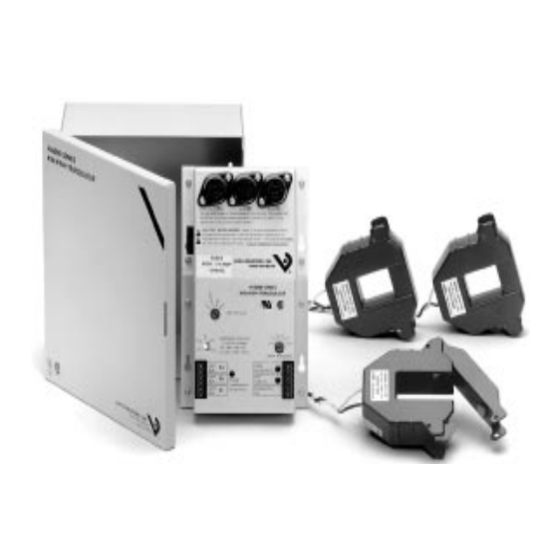
Easy installation
Small size (9.50" X 8.25" x 4.0") fits directly in
most panel enclosures.
Conduit ready enclosure for external mounting.
Hinged panel door
Direct voltage connection up to 600 VAC--no
expensive potential transformers (PTs)
Powered by voltage inputs
Easy field voltage selection (120 to 600 VAC)
4-20 mA output loop continuity LED
Pulse output rate LED
Accurate analog and pulse outputs
Accurate to +/- 0.5% of reading..true
RMS power!
4-20 mA output for demand KW
Pulse output for KWH...adjustable rate
compatible with all automation systems and
data loggers
Phase loss/reversal/low voltage alarm output to
protect valuable equipment
KW and/or KWH display options. Maintains
readings in event of power loss
SAFE CTs...eliminates need for costly CT
shorting bars
Current transformers (CTs) utilize accurate
1.0 V output...non hazardous, even if left
unshorted!
Eliminates need for current shorting bars
Choose from split-core or solid-core CTs
CT accuracy ± 1% from 1% to 100% of the
rating
Literature #L10159-1196
Installation Instructions
H-6001
KW/KWH Transducer
VERIS INDUSTRIES, INC.
10831 S.W. CASCADE BLVD.
PORTLAND, OREGON 97223
(503) 598-4564 FAX (503) 598-4664
http://www.veris.com
OPERATION
The H-6001 series 3-phase Power (KW) transducer is de-
signed for use in industrial, commercial, and building
automation KW and KWH applications.
The H-6001 accepts three Veris 1.0 V current transformer
inputs and three direct connect voltage inputs. The trans-
ducer multiplies the input current signal, voltage input,
and power factor for each phase to calculate true RMS
power (KW = E x I x 1.73 x power factor). The instantaneous
power (KW) of all three phases is summed and converted
to an industry-standard 4-20 mA output signal for use in
demand management (load shedding) applications. The
sensor also accumulates this instantaneous value over
time and produces a pulsed output proportional to the
energy usage (KWH). The frequency of the output pulses
is proportional to the total power consumed and can be
used to measure energy usage for an entire building,
selected area, or individual loads (chillers, compressors,
etc..).
WARNING--REFER SERVICING TO
!
QUALIFIED PERSONNEL ONLY!
• This product is not intended for life or safety
applications
• Potential electrocution hazard exists. Installing
sensors in an energized motor control center or
on any energized conductor can be hazardous.
• Read instructions thoroughly prior to install
Severe injury or death can result from electrical shock
during contact with high voltage conductors or related
equipment. Disconnect and lock-out all power sources
during installation and service. Applications shown
are suggested means of installing sensors, but it is the
responsibility of the installer to ensure that the instal-
lation is in compliance with all national and local
codes. Installation should be attempted only by indi-
viduals familiar with codes, standards, and proper
safety procedures for high-voltage installations.
1-800-354-8556
®
email:sales@veris.com
Advertisement
Table of Contents

Related Manuals for Veris H-6001


Summary of Contents for Veris H-6001
- Page 1 1-800-354-8556 ® http://www.veris.com email:sales@veris.com OPERATION The H-6001 series 3-phase Power (KW) transducer is de- Easy installation signed for use in industrial, commercial, and building automation KW and KWH applications. Small size (9.50" X 8.25" x 4.0") fits directly in most panel enclosures.
-
Page 2: General Wiring Diagram
For use with single or three phase AC circuits only, 120 to 600 VAC, 50–60 Hz. For single phase operation, connect L-1 and L-2 only. Maximum current consumption 50 mA. FUSES: 600 V 1/4 AMP, 100 KAIC 5892 VERIS INDUSTRIES, INC. 1-800-354-8556 ® kW (mA) H-6000 SERIES kW/kWH TRANSDUCER ®... - Page 3 SINGLE PHASE INSTALLATION ON THREE-PHASE SINGLE PHASE VOLTAGE WITH A NEUTRAL BALANCED LOADS (e.g., 120 V), the following installation instructions apply (see drawing below) Install one CT (must be on phase A current connection) and Install 1 CT on the "hot" lead per the installation instruc- connect all three voltage leads to A,B, and C voltage tions (i.e., arrows facing the load) and connect the leads connections.
- Page 4 OPTIONAL MONITORING OF MULTIPLE LOADS For use with line voltages in excess of 600V The Veris 6001 is extremely flexible and allows multiple sets of current sensors to be used in parallel so that multiple locations can be monitored by a single meter.
-
Page 5: Installation
8. SELECT KWH MAX. PULSE RATE (IF USED) Reversal On-Normal LED is illuminated. If the light is on Veris' handy pulse rate selector switch lets you choose the then the voltage wires are hooked up correctly. If the light pulse rate compatible with your panel--regardless of is not on the phasing is incorrect. -
Page 6: Troubleshooting
INSTALLATION CONTINUED TROUBLESHOOTING 10. DETERMINE KW VALUE FOR PROGRAMING YOUR Problem: Phase loss LED out. Solution: AUTOMATION PANEL. A. On initial installation, check L-1, L-2, L-3 to ensure phases are not reversed, and that all are connected. KW MAXIMUM = E x I x 1.73 1000 Check that voltages on phases are above undervoltage set-point. - Page 7 TABLE 1: WH/PULSE FACTOR SWITCH SELECTION: PULSES/SECOND 4 . 6 2 . 3 1 . 2 0 . 6 0 . 3 VOLTAGE 6 0 0 0.3125 0.6250 1.2500 2.5000 5.0000 4 8 0 0.2500 0.5000 1.0000 2.0000 4.0000 2 4 0 / 2 0 8 0.1250 0.2500 0.5000...
-
Page 8: Transducer Specifications
CURRENT TRANSFORMER SPECIFICATIONS Output at full-scale..........1.0 VAC Accuracy......± 1 from 1% to 100% of rating Leads.......22 PVC ETD twisted pair, Black/white, UL 1015, 8' length Important note: You may interface the transducer with 0-5 A CTs ONLY using H-6902 interface modules. Failure to interface properly will damage transducer, 0-5A CTs.
Need help?
Do you have a question about the H-6001 and is the answer not in the manual?
Questions and answers