Table of Contents
Advertisement
Quick Links
USER MANUAL AND SPECIFICATIONS
NI 9157/9159
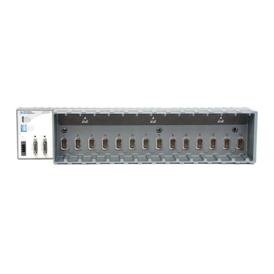
Reconfigurable Embedded Chassis with Integrated MXI-Express (x1)
1. LEDs
2. Upstream Port
3. MXI-Express LINK LEDs
This document describes how to connect the NI 9157/9159 to a MXI-Express host and one or
more other chassis, and how to use the features of the NI 9157/9159. This document also
contains specifications for the NI 9157/9159.
Safety Guidelines
Operate the NI 9157/9159 only as described in this document.
Caution
document. Product misuse can result in a hazard. You can compromise the safety
protection built into the product if the product is damaged in any way. If the product
is damaged, return it to NI for repair.
Figure 1. NI 9157/9159 Front Panel
1
POWER
P
USER FPGA1
USER FPGA1
USER FPGA2
USER FPGA2
USER FPGA3
USER FPGA3
6
INPUT
9-30 V
35W MAX
V1
C
V2
C
5
Do not operate the NI 9157/9159 in a manner not specified in this
2
NI 915X
MXI-Express RIO
NO FPGA APP
USER FPGA1
USER FPGA2
USER FPGA3
LINK
LINK
4. Downstream Port
5. Power Connector
6. DIP Switches
3
4
Advertisement
Table of Contents

Related Manuals for National Instruments NI 9159


Summary of Contents for National Instruments NI 9159
- Page 1 USER MANUAL AND SPECIFICATIONS NI 9157/9159 Reconfigurable Embedded Chassis with Integrated MXI-Express (x1) Figure 1. NI 9157/9159 Front Panel NI 915X MXI-Express RIO POWER USER FPGA1 USER FPGA1 USER FPGA2 USER FPGA2 USER FPGA3 USER FPGA3 NO FPGA APP USER FPGA1 USER FPGA2 USER FPGA3 LINK...
-
Page 2: Safety Guidelines For Hazardous Locations
Safety Guidelines for Hazardous Locations The NI 9157/9159 is suitable for use in Class I, Division 2, Groups A, B, C, D, T4 hazardous locations; Class I, Zone 2, AEx nA IIC T4 and Ex nA IIC T4 hazardous locations; and nonhazardous locations only. - Page 3 Panel mount kit (for panel mounting only) • Three M4 or number 8 panhead screws (for mounting the chassis without one of the listed mounting kits) • Number 2 Phillips screwdriver NI 9157/9159 User Manual and Specifications | © National Instruments | 3...
- Page 4 • Power supply • MXI-Express (x1) Series User Manual Note Visit ni.com/info and enter the Info Code rdsoftwareversion determine which software you need to use the NI 9157/9159. Mounting the NI 9157/9159 You can mount the chassis horizontally on a 35 mm DIN rail or on a flat, vertical, metallic surface such as a panel or wall.
- Page 5 132.6 mm (5.22 in.) (6.50 in.) 36.4 mm (1.43 in.) 88.1 mm (3.47 in.) 51.7 mm (2.04 in.) 4.1 mm Cooling Outline (0.16 in.) 50.8 mm (2 in.) NI 9157/9159 User Manual and Specifications | © National Instruments | 5...
-
Page 6: Mounting The Chassis On A Din Rail
Figure 5. NI 9157/9159, Side View with Dimensions 68.2 mm (2.68 in.) 51.4 mm (2.02 in.) 69.5 mm (2.74 in.) 44.1 mm (1.74 in.) 18.7 mm (0.74 in.) The following sections contain instructions for the mounting methods. Before using any of these mounting methods, record the serial number from the back of the chassis. - Page 7 Press down firmly on the chassis to compress the spring until the clip locks in place on the DIN rail. Caution Make sure that no I/O modules are in the chassis before removing it from the DIN rail. NI 9157/9159 User Manual and Specifications | © National Instruments | 7...
- Page 8 Mounting the Chassis on a Flat Surface Using the NI 9907 Panel Mount Kit Panel or wall mounting is the best method for applications that are subject to high shock and vibration. You can use the NI 9907 panel mount kit to mount the NI 9157/9159 on a flat surface.
-
Page 9: Installing C Series Modules
The following figure shows the mechanical dimensions of C Series I/O modules. Figure 11. C Series I/O Module, Front and Side View with Dimensions 88.1 mm (3.47 in.) 22.9 mm 70.7 mm (2.78 in.) (0.90 in.) NI 9157/9159 User Manual and Specifications | © National Instruments | 9... -
Page 10: Removing C Series Modules
Complete the following steps to install a C Series I/O module in the chassis. Make sure that no I/O-side power is connected to the I/O module. If the system is in a nonhazardous location, the chassis power can be on when you install I/O modules. Align the I/O module with an I/O module slot in the chassis. -
Page 11: Wiring Power To The Chassis
MXI-Express Host System or a Target Complete the following steps to connect one or more NI 9157/9159 chassis to a MXI-Express host system or a target. NI 9157/9159 User Manual and Specifications | © National Instruments | 11... - Page 12 Use the RIO Device Setup utility to select reset options. Access the RIO Device Setup utility by selecting Start»All Programs»National Instruments»NI-RIO»RIO Device Setup. Table 1. Chassis Powerup Options...
-
Page 13: Powering Down The Mxi-Express System
Push the NO FPGA APP switch to the ON position to prevent a LabVIEW FPGA application from loading at startup. The NO FPGA APP switch overrides the chassis powerup options NI 9157/9159 User Manual and Specifications | © National Instruments | 13... -
Page 14: Understanding Led Indications
described in the section on chassis powerup options. After startup you can download to the FPGA from software regardless of switch position. USER FPGA Switches You can define the USER FPGA switches for your application. Use the LabVIEW FPGA Module and NI-RIO software to define the USER FPGA switches to meet the needs of your application. -
Page 15: Power Requirements
Listed and LPS marks. The power supply must also meet any safety and compliance requirements for the country of use. Recommended power supply 55 W, 30 VDC maximum Voltage requirement 9 V to 30 V NI 9157/9159 User Manual and Specifications | © National Instruments | 15... -
Page 16: Physical Characteristics
Chassis power consumption/dissipation NI 9157 With no I/O modules 14.4 W (maximum) With 14 I/O modules 30.7 W (maximum) NI 9159 With no I/O modules 16.25 W (maximum) With 14 I/O modules 32.7 W (maximum) Note The power consumption specifications in this document are maximum values for a LabVIEW FPGA application compiled at 80 MHz. -
Page 17: Safety And Hazardous Locations Standards
EN 61326 (IEC 61326): Class A emissions; Industrial immunity • EN 55011 (CISPR 11): Group 1, Class A emissions • AS/NZS CISPR 11: Group 1, Class A emissions NI 9157/9159 User Manual and Specifications | © National Instruments | 17... -
Page 18: Online Product Certification
• FCC 47 CFR Part 15B: Class A emissions • ICES-001: Class A emissions Note For EMC declarations and certifications, and additional information, refer to Online Product Certification section. Note For EMC compliance, operate this product according to the documentation. CE Compliance This product meets the essential requirements of applicable European Directives, as follows: •... -
Page 19: Environmental Management
The NI website is your complete resource for technical support. At ni.com/support, you have access to everything from troubleshooting and application development self-help resources to email and phone assistance from NI Application Engineers. NI 9157/9159 User Manual and Specifications | © National Instruments | 19... - Page 20 CONTAINED HEREIN AND SHALL NOT BE LIABLE FOR ANY ERRORS. U.S. Government Customers: The data contained in this manual was developed at private expense and is subject to the applicable limited rights and restricted data rights as set forth in FAR 52.227-14, DFAR 252.227-7014, and DFAR 252.227-7015. © 2010—2016 National Instruments. All rights reserved. 375184E-01 Apr16...
Need help?
Do you have a question about the NI 9159 and is the answer not in the manual?
Questions and answers