Table of Contents
Advertisement
Quick Links
OPERATING INSTRUCTIONS AND SPECIFICATIONS
NI 9157/9159
Reconfigurable Embedded Chassis with Integrated MXI-Express (x1)
1
6
INPUT
9-30 V
35W MAX
V1
C
V2
C
5
1 LEDs
2 Upstream Port
3 MXI-Express LINK LEDs
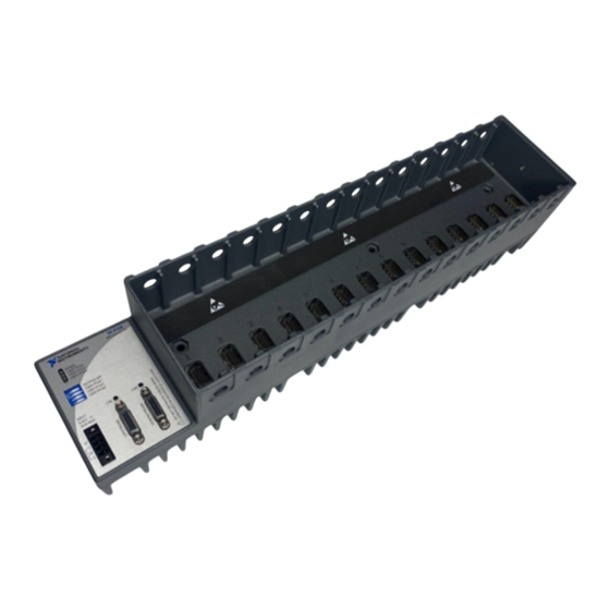
This document describes how to connect the NI 9157/9159 to a
MXI-Express host and one or more other chassis, and how to use
the features of the NI 9157/9159. This document also contains
specifications for the NI 9157/9159.
2
NI 915X
MXI-Express RIO
P
POWER
USER FPGA1
USER FPGA1
USER FPGA2
USER FPGA2
USER FPGA3
USER FPGA3
NO FPGA APP
USER FPGA1
USER FPGA2
USER FPGA3
LINK
LINK
4 Downstream Port
5 Power Connector
6 DIP Switches
Figure 1. NI 9157/9159
3
4
Advertisement
Table of Contents

Related Manuals for National Instruments NI 9157


Summary of Contents for National Instruments NI 9157
- Page 1 6 DIP Switches Figure 1. NI 9157/9159 This document describes how to connect the NI 9157/9159 to a MXI-Express host and one or more other chassis, and how to use the features of the NI 9157/9159. This document also contains...
-
Page 2: Safety Guidelines For Hazardous Locations
Operate the NI 9157/9159 only as described in these operating instructions. Safety Guidelines for Hazardous Locations The NI 9157/9159 is suitable for use in Class I, Division 2, Groups A, B, C, D, T4 hazardous locations; Class 1, Zone 2, AEx nA IIC T4 and Ex nA IIC T4 hazardous locations;... - Page 3 PC with MXI-Express PCI or PCIe device installed – NI Industrial Controller The NI 9157/9159 requires a host system with a PCI Express clock that complies Note with the PCI Express Specification. The NI 9157/9159 may not be compatible with systems using noncompliant clocks, particularly clocks with peak frequencies higher than 100 MHz.
- Page 4 Figure 2 shows the chassis mounted horizontally. Figure 2. NI 9157/9159 Mounted Horizontally Measure the ambient temperature at each side of the chassis, 63.5 mm (2.5 in.) from the side and 50.8 mm (2 in.) forward from the rear of the chassis, as shown in Figure 3.
- Page 5 50.8 mm (2 in.) 50.8 mm 406.3 mm (2 in.) (16 in.) 1 Measure ambient temperature here. Figure 3. NI 9157/9159, Bottom View with Dimensions 28.0 mm Cooling Outline (1.10 in.) 50.8 mm (2 in.) 165.1 mm 132.6 mm (6.50 in.) (5.22 in.)
-
Page 6: Mounting The Chassis On A Din Rail
DIN rail. Fasten the DIN rail clip to the chassis using a number 2 Phillips screwdriver and three M4 50 screws. National Instruments provides these screws with the DIN rail mount kit. Tighten the screws to a ... - Page 7 Figure 6. Installing the DIN Rail Clip on the NI 9157/9159 Insert one edge of the DIN rail into the deeper opening of the DIN rail clip, as shown in Figure 7. 1 DIN Rail Clip 2 DIN Rail Spring 3 DIN Rail Figure 7.
- Page 8 Tighten the screws to a maximum torque of 1.3 N m (11.5 lb in.). Figure 8. Installing the Panel Mounting Plate on the NI 9157/9159 NI 9157/9159 Operating Instructions and Specifications ni.com...
- Page 9 If you do not have the NI 9907 panel mount kit and do not require the portability that the NI 9907 affords, you can mount the NI 9157/9159 directly on a flat surface using the three mounting holes. Complete the following steps.
- Page 10 I/O modules. Align the I/O module with an I/O module slot in the chassis as shown in Figure 12. The module slots are labeled 1 to 14, left to right. NI 9157/9159 Operating Instructions and Specifications ni.com...
- Page 11 Squeeze the latches and insert the I/O module into the module slot. Press firmly on the connector side of the I/O module until the latches lock the I/O module into place. Repeat these steps to install additional I/O modules. © National Instruments Corporation NI 9157/9159 Operating Instructions and Specifications...
-
Page 12: Wiring Power To The Chassis
V and C terminals. Optionally, you can connect a second power supply to the other pair of V and C terminals. The chassis draws power from the power supply with the higher voltage. The NI 9157/9159 has one layer of reverse-voltage protection. Complete the following steps to connect a power supply to the chassis. - Page 13 NI 9157/9159 to the Upstream port of the next NI 9157/9159 in the chain. The maximum number of NI 9157/9159 chassis in a chain depends on the system Note configuration. For example, a PXI system with an NI PXI-8196 controller can support four chassis per chain.
- Page 14 Loads the FPGA bit stream from flash memory to the FPGA when the chassis powers on. If you want the NI 9157/9159 to autoload and run a VI at powerup, you must also configure the VI to autoload before you compile it. For more information about autoloading VIs, refer to LabVIEW FPGA Module Help.
-
Page 15: Powering Down The Mxi-Express System
Powering Down the MXI-Express System Always power down the host system before powering down any connected NI 9157/9159 chassis. When the host system is powered down, the order in which connected NI 9157/9159 chassis are powered down is not important. -
Page 16: Understanding Led Indications
Figure 14. NI 9157/9159 LEDs POWER LED The POWER LED is lit while the NI 9157/9159 is powered on. This LED is a bi-color LED. When the chassis is powered from V1, the POWER LED is lit green. When the chassis is powered from V2, the POWER LED is lit yellow. -
Page 17: Power Requirements
Power Requirements Caution You must use the NI 9157/9159 with a 9 to 30 VDC output, UL Listed, limited power source (LPS) supply. The power supply must bear the UL Listed and LPS marks. The power supply must also meet any safety and compliance requirements for the country of use. -
Page 18: Physical Characteristics
Torque for screw terminals.....0.5 to 0.6 N · m (4.4 to 5.3 lb · in.) Chassis weight ........2,231 g (78.7 oz) Environmental The NI 9157/9159 is intended for indoor use only. Operating temperature (IEC-60068-2-1 and IEC-60068-2-2) ..0 °C to 55 °C Note... -
Page 19: Shock And Vibration
EN 55011 (CISPR 11): Group 1, Class A emissions • AS/NZS CISPR 11: Group 1, Class A emissions • FCC 47 CFR Part 15B: Class A emissions • ICES-001: Class A emissions © National Instruments Corporation NI 9157/9159 Operating Instructions and Specifications... -
Page 20: Online Product Certification
Instruments WEEE initiatives, and compliance with WEEE Directive 2002/96/EC on Waste Electrical and Electronic Equipment, visit ni.com/environment/weee National Instruments (RoHS) National Instruments RoHS ni.com/environment/rohs_china (For information about China RoHS compliance, go to ni.com/environment/rohs_china NI 9157/9159 Operating Instructions and Specifications ni.com... -
Page 21: Hazardous Locations
Europe (DEMKO) ........Ex nA IIC T4 Where to Go for Support National Instruments corporate headquarters is located at 11500 North Mopac Expressway, Austin, Texas, 78759-3504. National Instruments also has offices located around the world to help address your support needs. - Page 22 For patents covering National Instruments products/technology, refer to the appropriate location: Help»Patents in your software, the patents.txt file on your media, or the National Instruments Patent Notice at ni.com/patents.
Need help?
Do you have a question about the NI 9157 and is the answer not in the manual?
Questions and answers