Table of Contents
Advertisement
Quick Links
Advertisement
Table of Contents

Related Manuals for National Instruments NI-9145


Summary of Contents for National Instruments NI-9145
- Page 1 NI-9145 Getting Started 2025-03-03...
-
Page 2: Table Of Contents
Resetting the NI-9145 Network Configuration ........ -
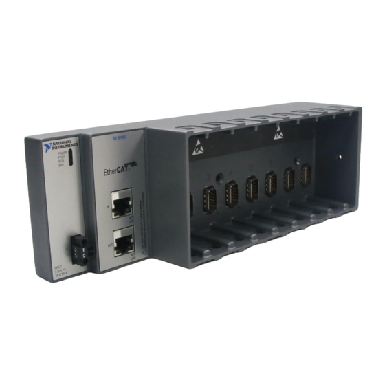
Page 3: Ni-9145 Front Panel
NI-9145 Front Panel NI-9145 NI-9145 Front Panel Front Panel 1. POWER LED 2. FPGA LED 3. RUN LED 4. ERR LED 5. Power Connector 6. Ethernet LEDs 7. Out Port 8. In Port © National Instruments... -
Page 4: Power Led Indicators
POWER LED Indicators The following table lists the POWER LED indicators. Table 1. POWER LED Indicators LED Color LED Pattern Indication The NI-9145 is powered on Green Solid and the connected power supply is adequate. — The NI-9145 is powered off. -
Page 5: Fpga Led
FPGA LED You can use the FPGA LED to help debug your application or easily retrieve application status. Use the LabVIEW FPGA Module and NI-RIO software to define the FPGA LED to meet the needs of your application © National Instruments... -
Page 6: Run Led Indicators
The following table lists the RUN LED indicators. Table 2. RUN LED Indicators LED Color LED Pattern Indication The NI-9145 is in initialize (INIT) run mode. The NI-9145 is initializing and discovering slaves. The NI-9145 is in pre- operational (PRE-OP) run Continuously blinks mode. - Page 7 RUN LED Indicators Figure 1. EtherCAT Modes INIT LabVIEW Configuration Mode PRE-OP Bootstrap SAFE-OP Operational LabVIEW Active Mode © National Instruments...
-
Page 8: Err Led Indicators
There is an unsolicited change Blinks once and pauses and the NI-9145 or module is in an emergency condition. There is an application watchdog timeout. The slave Blinks twice and pauses did not receive a scheduled EtherCAT telegram. -
Page 9: Safe-State Outputs
Safe-State Outputs Safe-State Outputs The NI-9145 has an EtherCAT safe state that the device passes through when moving from LabVIEW Active Mode to LabVIEW Configuration Mode. The NI-9145 passes through the EtherCAT safe state during normal operation or in case of a serious error. -
Page 10: Slave Timing Modes
0x3001.1 of the NI-9145. In synchronized mode, each conversion cycle begins with a signal from the EtherCAT master/scan engine. The NI-9145 procedures an error if the external cycle time is too fast for a module. NI Indcom for EtherCAT only supports synchronized mode. -
Page 11: Ni-9145 Block Diagram
NI-9145 Block Diagram NI-9145 NI-9145 Block Diagram Block Diagram FPGA Ethernet Port Ethernet Port Hardware Data NI 9145 © National Instruments... -
Page 12: Unpacking The Kit
Unpacking the Kit Unpacking the Kit Unpacking the Kit Notice To prevent electrostatic discharge (ESD) from damaging the device, ground yourself using a grounding strap or by holding a grounded object, such as your computer chassis. 1. Touch the antistatic package to a metal part of the computer chassis. 2. -
Page 13: Installing Software On The Host Computer
Installing Software on the Host Computer Installing Software on the Host Computer When using an NI master controller with the NI-9145, you must install the following application software and device drivers on the host computer in this order: 1. LabVIEW 2016 or later 2. -
Page 14: Connecting The Ni-9145
5. Grounding Terminal Connecting the Connecting the NI-9145 NI-9145 to Ground to Ground You must connect the NI-9145 grounding terminal to the grounding electrode system of the facility. What to Use • Ring lug • Wire, 1.31 mm (16 AWG) or larger •... -
Page 15: Connecting The Ni 9145 To Power
• Screwdriver, 2.54 mm (0.10 in.) flathead • Power supply, 9 V to 30 V, 20 Wminimum • Wire, 2.0 mm (14 AWG) or larger NI recommends the power supply listed in the following table for the NI-9145. © National Instruments... -
Page 16: Connecting The Ni 9145 To An Ni Master Controller
Connecting the NI-9145 Table 5. NI Power Supplies Power Supply Part Number NI PS-15 Industrial Power Supply (24 V DC, 5 A, 781093-01 100 V AC to 120 V AC/200 V AC to 240 V AC input) What to Do Complete the following steps to connect a power supply to the NI 9145. - Page 17 Connecting the NI-9145 NI recommends that you install a private network segment for your deterministic Ethernet expansion devices. Slave devices cause network flooding on a standard network. Non-EtherCAT frames jeopardize the system performance and determinism on an EtherCAT network. Refer to the EtherCAT Technology Group Web site at www.ethercat.org...
- Page 18 Connecting the NI-9145 the NI EtherCAT driver. ni.com...
-
Page 19: Mounting The Ni-9145
You can also mount the NI-9145 in other orientations, on a nonmetallic surface, on a 35-mm DIN rail, on a desktop, or in a rack. Mounting the NI-9145 in these or other configurations can reduce the maximum allowable ambient temperature and can affect the typical accuracy of modules in the NI-9145. -
Page 20: Mounting Requirements
Your installation must meet the following requirements for cooling and cabling clearance. Allow 25.4 mm (1.00 in.) on the top and the bottom of the NI-9145 for air circulation, as shown in the following figure. Figure 9. NI-9145 Cooling Dimensions 25.4 mm (1.00 in.) -
Page 21: Ambient Temperature
Ambient Temperature Measure the ambient temperature at each side of the NI-9145, 63.5 mm (2.50 in.) from the side and 25.4 mm (1.00 in.) forward from the rear of the NI-9145, as shown in the following figure. Figure 11. NI-9145 Ambient Temperature Location 25.4 mm... -
Page 22: Surface Mounting Dimensions
3. Fasten the NI 9145 to the surface using the M4 or number 8 screws appropriate for the surface. Tighten the screws to a maximum torque of 1.3 N · m(11.5 lb · in.). Surface Mounting Dimensions The following figure shows the surface mounting dimensions for the NI-9145. Figure 12. NI-9145 Surface Mounting Dimensions 30.8 mm (1.21 in.) - Page 23 Mounting the NI-9145 What to Use • NI 9145 • Screwdriver, Phillips #2 • NI panel mounting kit, 782863-01 ◦ Panel mounting plate ◦ M4 × 23 flathead screw (x3) What to Do Complete the following steps to mount the NI 9145 on a panel.
-
Page 24: Panel Mounting Dimensions
Mounting the NI-9145 Panel Mounting Dimensions The following figure shows the panel mounting dimensions for the NI-9145. Figure 13. NI-9145 Panel Mounting Dimensions 355.6 mm (14.00 in.) 336.5 mm (13.25 in.) 9.5 mm 7.2 mm (0.38 in.) 272.8 mm (0.29 in.) 17.6 mm... - Page 25 DIN rail clip. Clipping the Device on a DIN Rail Complete the following steps to clip the NI-9145 on a DIN rail. 1. Insert one edge of the DIN rail into the deeper opening of the DIN rail clip.
-
Page 26: Mounting The Controller On A Rack
Mounting the Controller on a Rack Mounting the Controller on a Rack You can use the following rack mount kits to mount the NI-9145 and other DIN rail- mountable equipment on a standard 482.6 mm (19 in.) rack. • NI Sliding Rack-Mounting Kit, 779102-01 •... -
Page 27: Desktop Mounting Dimensions
3. Align the brackets with the mounting holes on the ends of the NI 9145. 4. Use the Phillips #2 screwdriver to tighten the captive screws on the end of the brackets. Desktop Mounting Dimensions The following figures show the desktop mounting dimensions for the NI-9145. © National Instruments... -
Page 28: Upgrading From The Ni-9144 To The Ni-9145
NI-9145 NI-9145 You can use the NI-9144 to NI-9145 adapter panel mounting kit (NI part number 785984-01) to mount the NI-9145 to an existing NI-9144 panel mounting plate. Contact NI for information about ordering a NI-9144 to NI-9145 adapter panel mounting kit. - Page 29 Mounting the NI-9145 What to Do 1. Remove the NI 9144 from the NI 9144 panel mounting plate. 2. Align the adapter mounting plate with the holes in the NI 9144 panel mounting plate. 3. Fasten the adapter mounting plate to the NI 9144 panel mounting plate using the M4 or number 8 flathead screws.
- Page 30 Mounting the NI-9145 Figure 17. Attaching the NI 9145 to the Adapter Mounting Plate NI 9144 to NI 9145 Adapter Mounting Plate Dimensions 88.06 mm (3.467 in.) 272.80 mm (10.740 in.) ni.com...
-
Page 31: Updating Your Firmware
Firmware updates are performed by way of the File over EtherCAT (FoE) download protocol. All NI factory firmware update files have a .foe extension and have internal identification information that guides the NI-9145 during the update. Refer to your specific master software documentation for the procedure of sending FoE downloads. -
Page 32: Resetting The Ni-9145 Network Configuration
Resetting the NI-9145 Network Configuration Resetting the Resetting the NI-9145 NI-9145 Network Configuration Network Configuration To reset the NI-9145 network configuration, disconnect and reconnect the network cables on the NI-9145 chassis. ni.com... -
Page 33: Installing C Series Modules
Figure 18. Installing C Series Modules 1. Verify that power is not connected to the I/O connector(s) on the C Series module. If the system is in a nonhazardous location, the NI-9145 can be powered on when you install modules. -
Page 34: Vendor Extensions To The Object Dictionary
Vendor Extensions to the Object Dictionary Vendor Extensions to the Object Dictionary Most object dictionary entries are defined by the EtherCAT and CANOpen specifications for modular slave devices. The NI-9145 and the C Series modules have vendor extensions to those specifications. Note Visit ni.com/manuals... -
Page 35: Third-Party Master Controller
Third-Party Master Controller Third-Party Master Controller Third-Party Master Controller Refer to the EtherCAT® Expansion Chassis Vendor Configurations Guide for more information about integrating the NI-9145 with a third party master controller. © National Instruments © 2025 National Instruments Corporation.
Need help?
Do you have a question about the NI-9145 and is the answer not in the manual?
Questions and answers