Table of Contents
Advertisement
Quick Links
OPERATING INSTRUCTIONS AND SPECIFICATIONS
NI 9148
Ethernet Expansion Chassis for C Series Modules
1
POWER
USER FPGA1
STATUS
4
V
C
NC
C
3
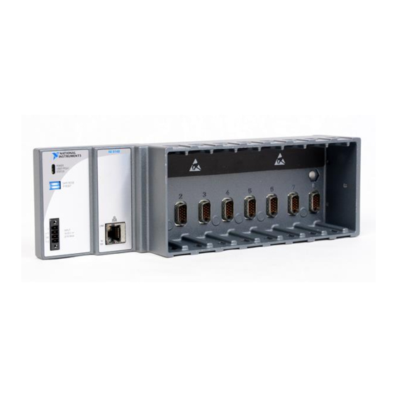
1 LEDs
2 RJ-45 Ethernet Port
This document describes how to connect the NI 9148 to a network and
how to use the features of the NI 9148. This document also contains
specifications for the NI 9148.
SAFE MODE
IP RESET
LINK
INPUT
19-30 V
20 W MAX
10/
100
3 Power Connector
4 DIP Switches
Figure 1. NI 9148 Front Panel
NI 9148
2
Advertisement
Table of Contents

Related Manuals for National Instruments NI 9148


Summary of Contents for National Instruments NI 9148
- Page 1 4 DIP Switches Figure 1. NI 9148 Front Panel This document describes how to connect the NI 9148 to a network and how to use the features of the NI 9148. This document also contains specifications for the NI 9148.
-
Page 2: Safety Guidelines
NI 9148. The NI 9148 may be shipped with a clear protective film cover on the front panel. You can remove the film cover before installing the NI 9148. Mounting the Chassis You can mount the chassis in any orientation on a 35 mm DIN rail or on a panel. - Page 3 (1.91 in.) 29 mm (1.14 in.) 58.9 mm (2.32 in.) 286.4 mm (11.28 in.) 3.3 mm (0.13 in.) Figure 2. NI 9148, Bottom View with Dimensions 165.1 mm (6.50 in.) 19 mm (0.75 in.) NI 9148 36.4 mm POWER USER FPGA1 STATUS (1.43 in.)
- Page 4 Caution Mounting the Chassis on a Panel You can use the NI 9905 panel mount kit to mount the NI 9148 on a flat surface. Complete the following steps. Fasten the chassis to the panel mount kit using a number 2 Phillips screwdriver and two M4 ×...
- Page 5 Figure 5. Installing the Panel Mount Accessory on the NI 9148 330.2 mm (13.00 in.) 311.2 mm (12.25 in.) 9.5 mm 28.1 mm (0.38 in.) (1.11 in.) 15.5 mm (0.61 in.) NI 9148 31.8 mm POWER USER FPGA1 STATUS (1.25 in.) 63.5 mm...
-
Page 6: Mounting The Chassis On A Din Rail
Fasten the DIN rail clip to the chassis using a number 2 Phillips screwdriver and two M4 × 16 screws. National Instruments provides these screws with the DIN rail mount kit. Figure 7. Installing the DIN Rail Clip on the NI 9148 NI 9148 Operating Instructions and Specifications ni.com... - Page 7 Figure 9 shows the mechanical dimensions of C Series I/O modules. 88.1 mm (3.47 in.) 22.9 mm 70.7 mm (0.9 in.) (2.78 in.) Figure 9. C Series I/O Module, Front and Side View with Dimensions © National Instruments Corporation NI 9148 Operating Instructions and Specifications...
- Page 8 Squeeze the latches and insert the I/O module into the module slot. Press firmly on the connector side of the I/O module until the latches lock the I/O module into place. Repeat these steps to install additional I/O modules. NI 9148 Operating Instructions and Specifications ni.com...
-
Page 9: Wiring Power To The Chassis
Wiring Power to the Chassis The NI 9148 requires an external power supply that meets the specifications in the Power Requirements section. The NI 9148 filters and regulates the supplied power and provides power for all of the I/O modules. - Page 10 The C terminals are internally connected to each other. Powering On the NI 9148 When you apply power to the NI 9148, the chassis runs a power-on self test (POST). During the POST, the Power and Status LEDs turn on. The Status LED turns off, indicating that the POST is complete.
-
Page 11: Configuring Ip Settings
Configuring IP Settings When you power on the NI 9148 for the first time, it boots into safe mode because there is no software installed on it. This section describes how to configure the IP settings and install software on the chassis. -
Page 12: Configuring Dip Switches
Safe mode is for troubleshooting, updating configuration, and installing software. Keep the SAFE MODE switch in the OFF position during normal operation. If the switch is in the ON position at startup, the NI 9148 launches only the essential services required for updating configuration and installing software. -
Page 13: Understanding Led Indications
STATUS Figure 13. NI 9148 LEDs POWER LED The POWER LED is lit while the NI 9148 is powered on. This LED indicates that the power supply connected to the chassis is adequate. USER FPGA1 LED You can use the USER FPGA LED to help debug your application or easily retrieve application status. - Page 14 If the problem persists, contact National Instruments. Troubleshooting Network Communication If the NI 9148 cannot communicate with the network, you can perform the following troubleshooting steps. Move the IP RESET switch to the ON position. Disconnect and reconnect chassis power.
-
Page 15: Specifications
Available embedded RAM..... 720 kbits Power Requirements Caution You must use a UL Listed ITE power supply marked LPS with the NI 9148. Recommended power supply ....48 W, 24 VDC Power consumption........ 20 W maximum Power supply input range....... 19 to 30 V Physical Characteristics If you need to clean the chassis, wipe it with a dry towel. -
Page 16: Safety Voltages
ICES-001: Class A emissions For the standards applied to assess the EMC of this product, refer to the Online Note Product Certification section. Note For EMC compliance, operate this product according to the documentation. NI 9148 Operating Instructions and Specifications ni.com... -
Page 17: Environmental Management
EU Battery Directive 2006/66/EC about Batteries and Accumulators and Waste Batteries and Accumulators, visit ni.com/environment/batterydirective National Instruments (RoHS) National Instruments RoHS ni.com/environment/rohs_china (For information about China RoHS compliance, go to ni.com/environment/rohs_china © National Instruments Corporation NI 9148 Operating Instructions and Specifications... -
Page 18: Shock And Vibration
Environmental The NI 9148 is intended for indoor use only, but it may be used outdoors if mounted in a suitably rated enclosure. Operating temperature (IEC 60068-2-1, IEC 60068-2-2) ...–40 to 70 °C Note To meet this operating temperature range, follow the guidelines in the installation instructions for your system. - Page 19 Connector 1 Connector 2 Pin 1 Pin 8 Pin 1 Pin 8 Figure 14. Ethernet Connector Pinout © National Instruments Corporation NI 9148 Operating Instructions and Specifications...
-
Page 20: Where To Go For Support
For patents covering National Instruments products/technology, refer to the appropriate location: Help»Patents in your software, the patents.txt file on your media, or the National Instruments Patent Notice at ni.com/patents.
Need help?
Do you have a question about the NI 9148 and is the answer not in the manual?
Questions and answers