Advertisement
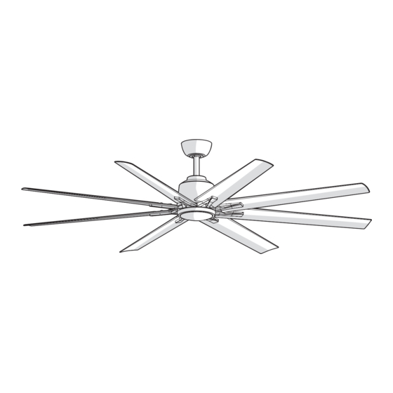
INDOOR/COVERED OUTDOOR CEILING FAN
Questions, problems, missing parts? Before returning to the store,
8 a.m. - 7 p.m., EST, Monday-Friday, 9 a.m. - 6 p.m., EST, Saturday
We appreciate the trust and confidence you have placed in Home Decorators Collection through the purchase of this ceiling fan. We
strive to continually create quality products designed to enhance your home. Visit us online to see our full line of products available for
your home improvement needs. Thank you for choosing Home Decorators Collection!
USE AND CARE GUIDE
72 IN KENSGROVE II
call Hubspace Customer Service
1-877-592-5233
HOMEDEPOT.COM/HUBSPACE
Visual instruction of how to install this fan:
Visit www.homedepot.com and enter either the Item or Model number to find
this fan and click the link of visual instruction in the product overview section.
Item #1008 622 049
Model #N608-BN
THANK YOU
1008 622 051
1008 622 432
1008 622 431
N608-MBK
N608-CB
N608-MWH
Advertisement

Subscribe to Our Youtube Channel
Related Manuals for Home Decorators Collection KENSGROVE II N608-BN


Summary of Contents for Home Decorators Collection KENSGROVE II N608-BN
- Page 1 THANK YOU We appreciate the trust and confidence you have placed in Home Decorators Collection through the purchase of this ceiling fan. We strive to continually create quality products designed to enhance your home. Visit us online to see our full line of products available for...
-
Page 2: Table Of Contents
Table of Contents Table of Contents ........Assembly . -
Page 3: Warranty
Warranty The manufacturer warrants the fan motor to be free from defects in workmanship and material present at time of shipment from the factory for a period of lifetime after the date of purchase by the original purchaser. The manufacturer warrants the light kit (excluding any glass), to be free from defects in workmanship and material present at time of shipment from the factory for a period of five years after the date of purchase by the original purchaser. - Page 4 Pre-Installation (continued) HARDWARE INCLUDED NOTE: Hardware not shown to actual size. Part Description Quantity Plastic wire nut Blade attachment screw and fiber washer 1.5V AAA battery 2-pin extension cord 3-pin extension cord...
- Page 5 Pre-Installation (continued) PACKAGE CONTENTS ON / OFF ON / OFF 6 SPEED BRIGHTNESS BREEZE COLOR TEMP. TIMER SUMMER WINTER FAN DIRECTION HOLD 3 SEC. Part Description Quantity Part Description Quantity Mounting bracket Blade Canopy Blade arm Canopy bottom cover (preassembled) 20 watt LED light kit assembly Hanger ball/downrod assembly Receiver...
-
Page 6: Installation
Installation MOUNTING OPTIONS WARNING: To reduce the risk of fire, electric shock, or NOTE: You may need a longer downrod to maintain proper personal injury, mount the fan to an outlet box marked blade clearance when installing on a steep, sloped ceiling. acceptable for fan support using the screws provided with the The maximum angle allowable is 18°... -
Page 7: Assembly
Assembly Preparing the canopy Preparing the motor Remove the cotter pin (GG) and clevis pin (HH), and loosen Remove the canopy bottom cover (C) from the canopy (B) by the two collar set screws (II) from the motor collar. turning the canopy bottom cover (C) counterclockwise. Take out the set screw (JJ) located in the hanger ball (KK), Remove the mounting bracket (A) from the canopy (B) by lower the hanger ball (KK) and remove the cross pin (LL). - Page 8 Assembly — Hanging the Fan Installing the mounting bracket to the Hanging the fan to the mounting electrical box bracket WARNING: To reduce the risk of fire, electric shock or other WARNING: The tab in the ring must rest in the groove of personal injury, mount the fan only to an outlet box or supporting the hanger ball/downrod assembly (D).
- Page 9 Assembly — Hanging the Fan (continued) Making the electrical connections Ground White Black conductor WARNING: Check to see that all connections are tight, including ground, and that no bare wire is visible at the wire nuts (except for the ground wire). CAUTION: To reduce the risk of electric shock, this fan must be installed with an isolating wall control/switch.
- Page 10 Assembly — Hanging the Fan (continued) Attaching the canopy Attaching the canopy bottom cover NOTE: Adjust the canopy mounting screws (FF) as necessary WARNING: Make sure the tab on the mounting bracket (A) until the canopy (B) and canopy bottom cover (C) are snug. properly sits in the groove in the hanger ball (KK) before attaching the canopy (B) to the mounting bracket (A) by turning the canopy housing until it drops into place.
- Page 11 Assembly — Attaching the Fan Blades Attaching the blades to the blade arms Attach the blades (G) to the blade arms (H) using the three blade attachment screws and fiber washers (BB). Insert a blade attachment screws and fiber washers (BB) into the blade arm (H), but do not tighten.
- Page 12 Assembly — Installing the Light Kit Installing the LED light kit to the light kit mounting plate CAUTION: Before starting installation, disconnect the power by turning off the circuit breaker or removing the fuse at the fuse box. Turning power off using the fan switch is not sufficient to prevent electric shock.
-
Page 13: Operation
Operation SETTING UP THE TRANSMITTER NOTE: The remote has been pre-paired in the factory for your convenience. NOTE: Batteries will weaken with age and should be replaced before leaking takes place as this will damage the remote control. Dispose of used batteries properly and keep them out of the reach of children. - Page 14 Operation (continued) OPERATING YOUR FAN AND REMOTE CONTROL NOTE: The fan will store the last used speed setting for the next time it is turned on. NOTE: On each start up of your ceiling fan, the fan blades will oscillate back and forth. This is a NORMAL OPERATION for DC motor ceiling fans as they go through a calibration cycle.
- Page 15 Operation (continued) INSTALLING THE REMOTE CONTROL HOLDER To install the remote control bracket (XX), remove the two screws holding the switch cover plate (YY). Do not remove the cover plate (YY). Orient the bracket (XX) by lining up the two mounting holes with those on the cover plate (YY).
-
Page 16: Care And Cleaning
Care and Cleaning Check the support connections, brackets, and blade attachments twice a year. Make sure they are secure. Because of the fan’s natural movement, some connections may become loose over time. It is not necessary to remove the fan from the ceiling. Clean your fan periodically. - Page 17 Application Set-Up NOTE: For more information on smart remote set up, please refer to the quick start guide located in the remote pack. NOTE: To use Alexa to change the white temperature of the Questions, problems missing parts? light, please make sure the light is turned on first. Please call Hubspace Customer service 8 a.m.
- Page 18 Voice Commands The Kensgrove II 72 in. LED Indoor Smart Color Changing Ceiling Fan works with Alexa and Google Assistant. This section lists some of the voice commands you can use. To view these and other commands, go to http://hubspaceconnect.com/. Google Alexa When you want to...
- Page 19 Troubleshooting (Hubspace Problem Solution My hubspace device is not Make sure your device is connected to a power source. connecting to Wi-Fi. Your Internet connection or Wi-Fi network may be down. My device cannot find any Make sure you have a 2.4GHz capable Wi-Fi network within range of the device you are trying to add. Wi-Fi networks.
- Page 20 This device complies with part 15 of the FCC Rules. Operation is subject to the following two conditions: (1) This device may not cause harmful interference, and (2) this device must accept any interference received, including interference that may cause undesired operation. WARNING: Changes or modifications to this unit not expressly approved by the party responsible for compliance could void the user's authority to operate the equipment.
Need help?
Do you have a question about the KENSGROVE II N608-BN and is the answer not in the manual?
Questions and answers
cam I get a replacement light anywhere for the Kensgrove II72" white fan?