Table of Contents
Advertisement
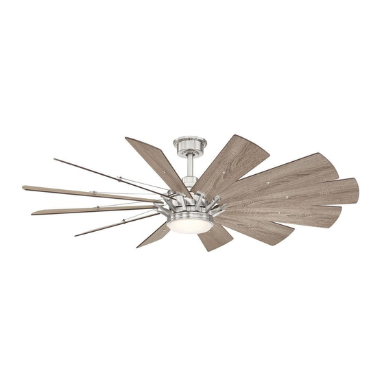
Item #731 152
Model #YG545-BN
USE AND CARE GUIDE
TRUDEAU 60 IN. CEILING FAN
Questions, problems, missing parts? Before returning to the store,
call Home Decorators Collection Customer Service
8 a.m. - 7 p.m., EST, Monday-Friday, 9 a.m. - 6 p.m., EST Saturday
1-800-986-3460
HOMEDEPOT.COM/HOMEDECORATORS
THANK YOU
THANK YOU
Advertisement
Table of Contents

Related Manuals for Home Decorators Collection Trudeau YG545-BN


Summary of Contents for Home Decorators Collection Trudeau YG545-BN
- Page 1 USE AND CARE GUIDE TRUDEAU 60 IN. CEILING FAN Questions, problems, missing parts? Before returning to the store, call Home Decorators Collection Customer Service 8 a.m. - 7 p.m., EST, Monday-Friday, 9 a.m. - 6 p.m., EST Saturday 1-800-986-3460 HOMEDEPOT.COM/HOMEDECORATORS...
-
Page 2: Table Of Contents
Table of Contents Table of Contents ............Operation ..............Setting the Code on the Transmitter ........Safety Information ............Learning Process ..............Operating Your Fan and Remote Control ........ Warranty ................. Reverse Switch Operating Instructions ........Pre-installation .............. Care and Cleaning ............Specifications ................ -
Page 3: Safety Information
Safety Information To reduce the risk of electric shock, ensure electricity has However, there is no guarantee that interference will not occur been turned off at the circuit breaker or fuse box before in a particular installation. If this equipment does cause harmful beginning. -
Page 4: Warranty
Warranty We warrant the fan motor to be free from defects in workmanship and material present at time of shipment from the factory for a period of lifetime after the date of purchase by the original purchaser. We also warrant that all other fan parts, excluding any glass or acrylic blades, to be free from defects in workmanship and material at the time of shipment from the factory for a period of two years after the date of purchase by the original purchaser. -
Page 5: Hardware Included
Pre-Installation (continued) HARDWARE INCLUDED HARDWARE INCLUDED NOTE: Hardware shown to actual size unless noted otherwise in the table below. Part Part Description Description Quantity Quantity Plastic wire nut (not to scale) Canopy mounting bracket screw with washer (preassembled) Blade attachment screw and fiber washer (not to scale) Blade arm screw and lock washer (preassembled) Clevis pin (preassembled) Cotter pin (preassembled) -
Page 6: Package Contents
Pre-Installation (continued) PACKAGE CONTENTS PACKAGE CONTENTS Part Part Description Description Quantity Quantity Part Part Description Description Quantity Quantity Mounting bracket (preassembled) Blade Canopy ring (preassembled) Blade arm Canopy Light kit mounting plate Hanger ball/downrod assembly 18 watt LED Light kit Coupling cover Glass shade Fan motor assembly... -
Page 7: Installation
Installation MOUNTING OPTIONS MOUNTING OPTIONS WARNING: NOTE: You may need a longer downrod to maintain proper To reduce the risk of fire, electric shock, or blade clearance when installing on a steep, sloped ceiling. personal injury, mount the fan to an outlet box marked acceptable for fan support using the screws provided with the The maximum angle allowable is 18°... -
Page 8: Assembly
Assembly Preparing the canopy Preparing the motor □ □ Remove the cotter pin (FF) and clevis pin (EE), and Remove the canopy ring (B) from the canopy (C). loosen the two collar setscrews (II) from the motor collar. □ Remove the two non-slotted mounting bracket screws (BB) from the canopy (C), and loosen the slotted □... -
Page 9: Hanging The Fan
Assembly — Hanging the Fan Hanging the fan to the mounting Installing the mounting bracket bracket to the electrical box WARNING: To reduce the risk of fire, electric shock or WARNING: The tab in the ring must rest in the groove of other personal injury, mount the fan only to an outlet box or the hanger ball/downrod assembly (D). - Page 10 Assembly — Hanging the Fan (continued) Making the electrical connections Ground Black White WARNING: To avoid possible electrical shock, be sure conductor electricity is turned off at the main fuse box before wiring. WARNING: Check to see that all connections are tight, including ground, and that no bare wire is visible at the wire nuts (except for the ground wire).
- Page 11 Assembly — Hanging the Fan (continued) Installing the canopy WARNING: Make sure the tab on the mounting bracket (A) properly sits in the groove in the hanger ball/downrod assembly (D) before attaching the canopy (C) to the mounting bracket (A) by turning the canopy (C) until it drops into place. WARNING: The locking slots of the canopy (C) are provided only as an aid to mounting.
- Page 12 Assembly — Attaching the Fan Blades Attaching the blades to the Fastening the blade blade arms assemblies to the motor □ Attach the blades (H) to the blade arms (I) using the WARNING: To reduce the risk of personal injury, do not three blade attachment screws and fiber washers bend the blade arms (I) while installing, balancing the blades (CC).
-
Page 13: Attaching The Fan Blades
Assembly — Attaching the Fan Blades (continued) Attaching the decorative rod □ Use the 1.5mm Allen wrench (NN) to loosen the Allen setscrews (MM) on end of the decorative rod (G). □ Rotate the decorative rods (G) onto the setscrew (WW) on the motor housing. -
Page 14: Installing The Light Kit
Assembly — Installing the Light Kit Attaching the light kit mounting Attaching the LED light kit plate to the mounting ring and glass shade □ Remove one of the three light kit mounting plate CAUTION: Before starting installation, disconnect the screws (OO) from the mounting ring (XX) and loosen power by turning off the circuit breaker or removing the fuse the other two screws. -
Page 15: Operation
Operation SETTING THE CODE ON THE TRANSMITTER NOTE: The battery will weaken with age and should be replaced before leaking takes place as this will damage the remote control. Dispose of used battery properly and keep the battery out of the reach of children. NOTE: The switch marked ON/DIM controls the dimming function of the lights. -
Page 16: Operating Your Fan And Remote Control
Operation (continued) OPERATING YOUR FAN AND REMOTE CONTROL button. - Press and release the button to turn the fan on or off. □ Press and hold the button for 5 seconds to enter the learning function. □ Fan on. The fan memory function will resume the speed set on the fan prior to the power being turned off. The LED bar will display the current settings for 5 seconds after the button is released. -
Page 17: Reverse Switch Operating Instructions
Operation Timer □ Pressing the timer button will automatically turn fan and light (if light is on) off after 2, 4, or 8 hours. When you activate the timer mode, the LED to the left of the time above the clock will illuminate. Disables timer Fan reverse button (Must be pushed when the fan is in operation) □... -
Page 18: Care And Cleaning
Care and Cleaning Do Do Do not Do not □ □ Check the support connections, brackets, and blade Use water when cleaning. Water could damage the motor, attachments twice a year. Make sure they are secure. or the wood, or possibly cause an electrical shock. Because of the fan’s natural movement, some □... - Page 19 Troubleshooting (continued) Problem Problem Solution Solution □ Do not connect the fan with wall mounted variable speed control(s). The remote control is not working. □ Make sure the frequency switches are set correctly. □ Verify that all blades and blade bracket screws are secure (most fan wobble problems are caused by loose parts).
-
Page 20: Service Parts
Service Parts Part Part Description Description Part Part Description Description Mounting bracket (preassembled) Blade attachment screw and fiber washer Canopy ring (preassembled) Blade arm screw and lock washer (preassembled) Canopy Clevis pin (preassembled) Hanger ball/downrod assembly Cotter pin (preassembled) Coupling cover Cross pin (preassembled) Fan motor assembly Setscrew (preassembled) - Page 21 Questions, problems, missing parts? Before returning to the store, call Home Decorators Collection Customer Service 8 a.m. - 7 p.m., EST, Monday-Friday, 9 a.m. - 6 p.m., EST Saturday 1-800-986-3460 HOMEDEPOT.COM/HOMEDECORATORS Retain this manual for future use. YG545BN0001-Y...
Need help?
Do you have a question about the Trudeau YG545-BN and is the answer not in the manual?
Questions and answers