Table of Contents
Advertisement
Quick Links
Advertisement
Table of Contents

Related Manuals for Pfeiffer Vacuum HEPTA 400 P


Summary of Contents for Pfeiffer Vacuum HEPTA 400 P
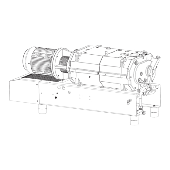
- Page 1 OPERATING INSTRUCTIONS Translation of the Original HEPTA 400 P Screw pump...
- Page 2 Dear Customer, Thank you for choosing a Pfeiffer Vacuum product. Your new screw pump is designed to support you with its performance, perfect operation and without impacting your individual application. The name Pfeiffer Vacuum represents high-quality vacuum technology, a comprehensive and complete range of top-quality products and first-class service. With this expertise, we have acquired a multitude of skills contributing to an efficient and secure implementation of our product.
-
Page 3: Table Of Contents
Table of contents Table of contents About this manual Validity 1.1.1 Applicable documents 1.1.2 Variants Target group Conventions 1.3.1 Instructions in the text 1.3.2 Pictographs 1.3.3 Stickers on the product 1.3.4 Abbreviations Trademark proof Safety General safety information Safety instructions Safety precautions Limits of use of the product Proper use... - Page 4 Decommissioning Decommissioning the vacuum pump Recommissioning Recycling and disposal General disposal information Disposing of the screw pump Malfunctions Service solutions by Pfeiffer Vacuum Accessories 12.1 Accessory information 12.2 Ordering accessories 12.3 Consumables Technical data and dimensions 13.1 General 13.2 Technical data 13.3 Substances in contact with the media...
- Page 5 Troubleshooting Tbl. 11: Accessories Tbl. 12: Consumables Tbl. 13: Conversion table: Pressure units Tbl. 14: Conversion table: Units for gas throughput Tbl. 15: Technical data for Hepta 400 P Tbl. 16: Materials that make contact with the process media 5/62...
- Page 6 Filling lubricant on the motor side Fig. 37: Filling lubricant on the vacuum side Fig. 38: Draining the cooling liquid Fig. 39: Filling the cooling liquid Fig. 40: Changing the gas ballast filter Fig. 41: Dimensions of Hepta 400 P 6/62...
-
Page 7: About This Manual
Keep the manual for future consultation. 1.1 Validity This operating instructions is a customer document of Pfeiffer Vacuum. The operating instructions de- scribe the functions of the named product and provide the most important information for the safe use of the device. The description is written in accordance with the valid directives. The information in this op- erating instructions refers to the product's current development status. -
Page 8: Pictographs
Rating plate (example) Rating plate for the screw pump Year 2019 D-35614 Asslar Made in Germany Vacuum Pump Hepta 400 P S/N = PPPPYYWWNNNN = 1 hPa (mbar) = 300 m³/h m = 500 kg = 3600 min Oil = Pfeiffer D1... -
Page 9: Abbreviations
About this manual 1.3.4 Abbreviations Abbreviation Meaning in this document Operating instructions Fluorocarbon rubber N.N. Mean sea level Protective earth (earthed conductor) Width Across Flats Standard liter per minute Thermal circuit breaker Volatile Corrosion Inhibitor Tbl. 2: Abbreviations used in this document 1.4 Trademark proof ●... -
Page 10: Safety
Safety 2 Safety 2.1 General safety information The following 4 risk levels and 1 information level are taken into account in this document. DANGER Immediately pending danger Indicates an immediately pending danger that will result in death or serious injury if not observed. ►... - Page 11 Safety Risks during installation DANGER Danger to life from electric shock Touching exposed and voltage-bearing elements causes an electric shock. Improper connection of the mains supply leads to the risk of touchable live housing parts. There is a risk to life. ►...
- Page 12 Safety WARNING Health hazard through poisoning from toxic contaminated components or devices Toxic process media result in contamination of devices or parts of them. During maintenance work, there is a risk to health from contact with these poisonous substances. Illegal disposal of toxic sub- stances causes environmental damage.
-
Page 13: Safety Precautions
► Observe the unit protection class prior to installation or operation in other environments. ► Provide suitable touch protection, if the surface temperature exceeds 70 °C. 2.4 Limits of use of the product Parameter Hepta 400 P Installation location ● Indoors, protected from dust deposits ● Outdoors, protected from direct weather influences Installation altitude max. -
Page 14: Proper Use
► Adhere to the installation, commissioning, operating, and maintenance instructions. ► Use only accessory parts recommended by Pfeiffer Vacuum. 2.6 Foreseeable improper use Improper use of the product invalidates all warranty and liability claims. Any use that is counter to the purpose of the product, whether intentional or unintentional, is regarded as improper use;... -
Page 15: Personnel Qualification For Maintenance And Repair
2.7.2 Personnel qualification for maintenance and repair Adequately trained individuals are: ● Maintenance level 1 ─ Customer with technical education ─ Pfeiffer Vacuum service technician ● Maintenance level 3 ─ Pfeiffer Vacuum service technician 15/62... -
Page 16: Product Description
Product description 3 Product description 3.1 Function The HeptaDry screw pumps function according to the double screw-pump principle. Two screw rotors rotate in the compression chamber. The medium to be pumped is trapped between the individual screw coils, compacted and transported to the gas outlet. During the compression process, the two screw ro- tors do not come into contact with each other or with the suction chamber. -
Page 17: Temperature Monitoring
The non-return valve prevents backflow of exhausted gases. 3.2 Identifying the product ► To ensure clear identification of the product when communicating with Pfeiffer Vacuum, always keep all of the information on the rating plate to hand. ► Observe the motor-specific data on the motor rating plate attached separately. -
Page 18: Transportation And Storage
► Always transport the screw pump without lubricant. ► Only fill up lubricant at the final installation location. Preparations for transport Pfeiffer Vacuum recommends keeping the transport packaging and original protective cov- Safe transport of the product ► Observe the weight specified on the packaging. -
Page 19: Bearing
5. Always place the vacuum pump on an adequately sized, level surface. 4.2 Bearing Storage Pfeiffer Vacuum recommends storing the products in their original transport packaging. Store the vacuum pump 1. Seal the vacuum and exhaust connection. 2. Make sure that the gas ballast valve is closed. -
Page 20: Installation
► Never insert hands or fingers into the vacuum connection. NOTICE Property damage from contaminated gases Pumping gases that contain contamination damages the vacuum pump. ► Use suitable filters or separators from the Pfeiffer Vacuum range of accessories, to protect the vacuum pump. 20/62... -
Page 21: Tbl. 5: Maximum Permissible Forces On The Intake Flange
The loading capacity is specific for the screw pump used. The total weight of superstructural parts must not exceed the maximum values specified. Installation and operation of accessories Pfeiffer Vacuum offers a wide range of specially tailored accessories for your screw pumps. ● Information and ordering options for approved accessories can be found online. -
Page 22: Connecting The Exhaust Side
Pfeiffer Vacuum recommends installing a condensate separator, with condensate drain at the lowest point of the exhaust line. Installation and operation of accessories Pfeiffer Vacuum offers a wide range of specially tailored accessories for your screw pumps. ● Information and ordering options for approved accessories can be found online. -
Page 23: Fig. 6: Connecting The Sealing Gas System
Installation Fig. 6: Connecting the sealing gas system 1 Flow regulator Sealing gas connection 2 Flow rate meter Pressure gauge 3 Pressure regulating valve Fig. 7: Connecting the sealing gas system with nitrogen monitoring tablet 1 Flow rate meter, flow rate monitor Pressure gauge 2 Solenoid valve Pressure regulating valve... -
Page 24: Connecting The Gas Ballast System
Installation 1(+) 2 (-) Fig. 9: Connection data for the flow rate monitor ● Pin 1 = Brown ● Pin 2 = White ● U = 5 to 25 V; I=1 to 3 mA ● Switching element function: NAMUR, bistable ●... -
Page 25: Connecting The Flushing Gas System
Installation ● U = 24 V DC; P = 8 W ● Contact: Normally closed Gas type Dry nitrogen Gas temperature 0 – 60 °C Max. gas pressure 13000 hPa Recommended pressure setting at the pressure regulating valve 500 hPa Filtration 5 μm Recommended flow rate... -
Page 26: Installing The Coupling
4. Mount the motor onto the screw pump using the coupling gear ring. 5.8 Connecting the silencer Installation and operation of accessories Pfeiffer Vacuum offers a wide range of specially tailored accessories for your screw pumps. ● Information and ordering options for approved accessories can be found online. -
Page 27: Filling The Cooling Liquid
Property damage as a result of inadequate cooling Inadequate cooling may cause damage to the vacuum pump. ► Only use the cooling liquid prescribed by Pfeiffer Vacuum (Zitrec M 25). ► Evacuate the cooling chambers following repairs and fill cooling liquid. -
Page 28: Filling With Lubricant
► Please refer to rating plate of the vacuum pump for type and quantity of intended lubricant. – Only the lubricant used during initial installation is permissible. ► Contact Pfeiffer Vacuum if you want to use another type of lubricant. 28/62... -
Page 29: 1Filling Lubricant On The Motor Side
Installation Required consumable material ● Lubricant Required tools ● Allen key, WAF 10 Required aids ● Funnel (optional) 5.10.1 Filling lubricant on the motor side Fig. 17: Filling lubricant on the motor side 1 Filler screw Sight glass Procedure 1. Unscrew the filler screw. 2. -
Page 30: Connect To Mains Power Supply
Installation Procedure 1. Unscrew the filler screw. 2. Fill up with lubricant according to the marks on the sight glass. 3. Screw in the filler screw. 4. Check the fill level during operation when running with final pressure. 5.11 Connect to mains power supply DANGER Danger to life from electric shock Touching exposed and voltage-bearing elements causes an electric shock. -
Page 31: 1Connect Three Phase Motor With 6-Pin Terminal Board
Installation 5.11.1 Connect three phase motor with 6-pin terminal board There are 2 circuit arrangements: ● Delta connection for low voltage ● Star circuit for high voltage Fig. 19: Delta connection Connect the three phase motor with delta connection ► Connect the three phase motor according to the connection diagram. Fig. -
Page 32: Checking The Direction Of Rotation
Installation Fig. 22: Delta connection Connect the three phase motor with delta connection ► Connect the three phase motor according to the connection diagram. Fig. 23: Star circuit Connect the three phase motor with star circuit ► Connect the three phase motor according to the connection diagram. 5.12 Checking the direction of rotation NOTICE Motor damage from overheating... -
Page 33: Connecting The Water/Air Heat Exchanger
Installation Procedure 1. Switch on the vacuum pump briefly (2 to 3 seconds). 2. Check the fan’s rotation of direction on the motor. The motor fan and the coupling rotate in a clockwise direction. 3. If the direction of rotation is incorrect, exchange the 2 phases of the connecting cable in the motor terminal box. -
Page 34: Connecting The Ptc Thermistor Tripping Unit
● P (50/60 Hz) = 0.21/0.29 kW 5.14 Connecting the PTC thermistor tripping unit Tripping units store the shut-down Pfeiffer Vacuum recommends connecting motors with PTC in the stator winding to a PTC resistor tripping device for protection against overload. 34/62... -
Page 35: Fig. 29: Connection Example With Ptc Thermistor Tripping Unit
Installation F1 - F3 AC 220 ... 240 V T1...T3 Fig. 29: Connection example with PTC thermistor tripping unit Control voltage T1 – T3 PTC resistor sensor OFF button Tripping indicator ON button Motor, 3-phase RESET button For devices with two relay outputs only Contactor For MSR type (model) only F1 –... -
Page 36: Operation
NOTICE Property damage from contaminated gases Pumping gases that contain contamination damages the vacuum pump. ► Use suitable filters or separators from the Pfeiffer Vacuum range of accessories, to protect the vacuum pump. NOTICE Property damage due to a lack of cooling If operation is carried out without air cooling, the screw pump may sustain damage. -
Page 37: Switching On The Vacuum Pump
Operation 6.2 Switching on the vacuum pump CAUTION Health hazard from increased noise emission Remaining in the close proximity of the vacuum pump for a sustained period of time may cause hear- ing damage. ► Ensure adequate sound insulation. ► Wear hearing protection. NOTICE Damage to the vacuum pump due to intense temperature fluctuations If the housing cools down too quickly due to external influences, there is a risk of contact between the... -
Page 38: Flushing The Screw Pump With Fluid
Operation 4. Allow the screw pump to run for 30 minutes in order to heat up. 5. Open the shut-off valve on the vacuum line. 6. Allow the condensate to discharge continuously for 30 minutes. 7. Close the shut-off valve on the vacuum line. 8. - Page 39 Operation 5. Ensure that you do not vent the vacuum chamber through the screw pump. 6. Switch off the process- and pump-specific media supply (e.g. the sealing gas supply). 39/62...
-
Page 40: Maintenance
Maintenance 7 Maintenance 7.1 Maintenance information WARNING Health hazard through poisoning from toxic contaminated components or devices Toxic process media result in contamination of devices or parts of them. During maintenance work, there is a risk to health from contact with these poisonous substances. Illegal disposal of toxic sub- stances causes environmental damage. -
Page 41: Checklist For Inspection And Maintenance
Level 1 and Maintenance Level 3 (revision). If the required intervals listed below are exceeded, or if maintenance work is carried out improperly, no warranty or liability claims are accepted on the part of Pfeiffer Vacuum. This also applies wherever parts other than original spare parts are used. -
Page 42: Checking The Cooling Liquid Level
Maintenance Fig. 31: Checking the lubricant level on the motor side Fig. 32: Checking the lubricant level on the vacuum side Checking the lubricant level 1. Shut down the vacuum pump. 2. Wait for 1 minute and check the lubricant level at the sight glass. –... - Page 43 The correct fill level is between the MIN/MAX markings or within the ring mark on the sight glass. Safety data sheets You can obtain the safety data sheets for lubricants from Pfeiffer Vacuum on request, or from the Pfeiffer Vacuum Download Center.
-
Page 44: Draining Lubricant On The Motor Side
Maintenance 7.5.1 Draining lubricant on the motor side Fig. 34: Draining lubricant on the motor side 1 Magnetic sealing plugs Drain screw 2 Collection receptacle Procedure 1. Place a collection receptacle beneath the drain hole on the motor side. 2. Unscrew the drain screw. 3. -
Page 45: Filling Lubricant On The Motor Side
Maintenance 5. Clean the magnetic sealing plug. 6. Screw in the magnetic sealing plug and drain screw. 7.5.3 Filling lubricant on the motor side Fig. 36: Filling lubricant on the motor side 1 Filler screw Sight glass Procedure 1. Unscrew the filler screw. 2. -
Page 46: Changing The Cooling Liquid
Property damage as a result of inadequate cooling Inadequate cooling may cause damage to the vacuum pump. ► Only use the cooling liquid prescribed by Pfeiffer Vacuum (Zitrec M 25). ► Evacuate the cooling chambers following repairs and fill cooling liquid. -
Page 47: Filling The Cooling Liquid
Property damage as a result of inadequate cooling Inadequate cooling may cause damage to the vacuum pump. ► Only use the cooling liquid prescribed by Pfeiffer Vacuum (Zitrec M 25). ► Evacuate the cooling chambers following repairs and fill cooling liquid. -
Page 48: Changing The Gas Ballast Filter
Maintenance 7.7 Changing the gas ballast filter The gas ballast filter is soiled if the vacuum pump takes in ambient air containing dust during gas ballast operation. As the soiling increases, the throughput of the gas ballast filter decreases. The risk of con- densation and corrosion in the vacuum pump increases. - Page 49 Maintenance Cleaning the non-return flap Clean the non-return flap as a function of the process approx. every 1000 h with a suitable cleaning agent. 1. Check the functionality of the non-return flap. 2. If necessary, disconnect the non-return flap. 3. Clean and dry the non-return flap thoroughly. 49/62...
-
Page 50: Decommissioning
► Change the lubricant. ► Replace the bearing and elastomer parts. ► Observe the maintenance instructions. ► Consult Pfeiffer Vacuum if necessary. Procedure when recommissioning the vacuum pump 1. Put the vacuum pump into operation only if it is in a correct state. - Page 51 Decommissioning 3. Screw in the closing screw. 4. Switch the vacuum pump on. 51/62...
-
Page 52: Recycling And Disposal
– Potentially contaminated components that come into contact with media 9.2 Disposing of the screw pump Pfeiffer Vacuum screw pumps from the HeptaDry series contain materials which must be recycled. 1. Fully drain the lubricant. 2. Fully drain the cooling liquid. -
Page 53: Malfunctions
► Wear personal protective equipment if necessary. NOTICE Danger of property damage from improper maintenance Unprofessional work on the vacuum pump will lead to damage for which Pfeiffer Vacuum accepts no liability. ► We recommend taking advantage of our service training offering. -
Page 54: Tbl. 10: Troubleshooting
The cooling liquid pump is de- ● Have the vacuum pump repaired. fective ● Contact Pfeiffer Vacuum Service. ● The water/air heat exchang- ● Clean the water/air heat exchanger. er is dirty or clogged ● Ensure that the air current is not im- peded. -
Page 55: Service Solutions By Pfeiffer Vacuum
We are always focused on perfecting our core competence – servicing of vacuum components. Once you have purchased a product from Pfeiffer Vacuum, our service is far from over. This is often exactly where service begins. Obviously, in proven Pfeiffer Vacuum quality. - Page 56 Service solutions by Pfeiffer Vacuum 5. Prepare the product for transport in accordance with the provisions in the contamination declaration. a) Neutralize the product with nitrogen or dry air. b) Seal all openings with blind flanges, so that they are airtight.
-
Page 57: Accessories
PTC-resistor tripping device for motor protection 220 – 240 V AC P 4768 052 FQ Exhaust silencer DN 80, PN 16 PU Z00 102 Non-return flap Hepta 400 P/630 P PU Z00 202 SAS 63, dust separator, DN 63 ISO-K PK Z60 511 Tbl. -
Page 58: Technical Data And Dimensions
5 – 55 °C Weight 500 kg Tbl. 15: Technical data for Hepta 400 P 13.3 Substances in contact with the media Check whether the following materials are chemically resistant to the process media being conveyed. Pump parts Substances in contact with the media... -
Page 59: Dimensions
Tbl. 16: Materials that make contact with the process media 13.4 Dimensions 1025 Ø 75 1420 4x M12 1492 A ( 1 : 5 ) PN6 DN 80 ISO-K DN 63 Fig. 41: Dimensions of Hepta 400 P Dimensions in mm 59/62... -
Page 60: Ec Declaration Of Conformity
DIN EN IEC 61000-6-4: 2020 DIN EN ISO 2151: 2009 DIN EN ISO 13849-1: 2016 The authorized representative for the compilation of technical documents is Dr. Adrian Wirth, Pfeiffer Vacuum GmbH, Berliner Straße 43, 35614 Asslar, Germany. Signature: Pfeiffer Vacuum GmbH Berliner Straße 43... -
Page 61: Declaration Of Conformity
EN ISO 2151: 2008 EN ISO 13849-1: 2016 The manufacturer's authorized representative in the United Kingdom and the authorized agent for compiling the technical documentation is Pfeiffer Vacuum Ltd, 16 Plover Close, In- terchange Park, MK169PS Newport Pagnell. Signature: Pfeiffer Vacuum GmbH Berliner Straße 43... - Page 62 Notizen / Notes:...
Need help?
Do you have a question about the HEPTA 400 P and is the answer not in the manual?
Questions and answers