Pfeiffer Vacuum HEPTA 100 P Operating Instructions Manual
Screw pump
Hide thumbs
Also See for HEPTA 100 P:
- Operating instructions manual (72 pages) ,
- Operating instructions manual (140 pages)

Related Manuals for Pfeiffer Vacuum HEPTA 100 P


Summary of Contents for Pfeiffer Vacuum HEPTA 100 P
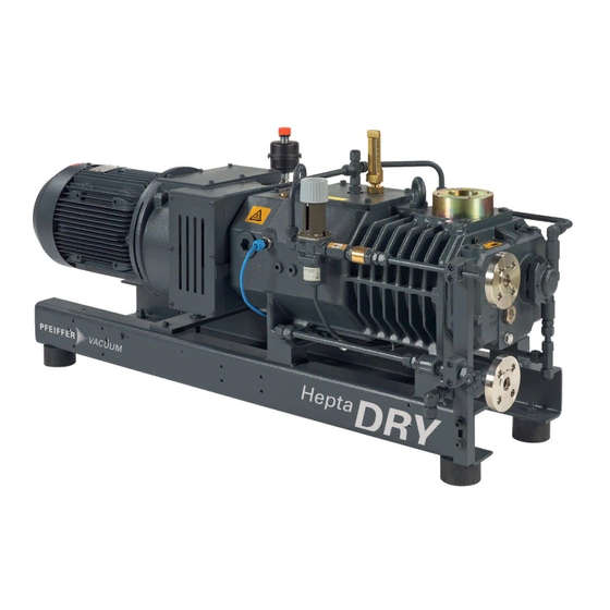
- Page 1 OPERATING INSTRUCTIONS Translation of the Original HEPTA 100 | 200 | 300 P Screw pump...
- Page 2 Dear Customer, Thank you for choosing a Pfeiffer Vacuum product. Your new screw pump is designed to support you with its performance, perfect operation and without impacting your individual application. The name Pfeiffer Vacuum stands for high-quality vacuum technology, a comprehensive and complete range of top-quality products and first-class service.
-
Page 3: Table Of Contents
Connecting the flushing gas system Installing the coupling Filling the cooling liquid 5.9.1 Filling up the cooling liquid on the Hepta 100 P 5.9.2 Filling up the cooling liquid on the Hepta 200 P | 300 P 5.10 Filling with lubricant 5.10.1Filling up lubricant on the motor side... - Page 4 7.6.1 Draining the cooling liquid on the Hepta 100 P 7.6.2 Draining the cooling liquid on the Hepta 200 | 300 P 7.6.3 Filling up the cooling liquid on the Hepta 100 P 7.6.4 Filling up the cooling liquid on the Hepta 200 P | 300 P...
- Page 5 Conversion table: Units for gas throughput Tbl. 19: Materials that make contact with the process media Tbl. 20: Technical data for Hepta 100 P Tbl. 21: Technical data for Hepta 200 P Tbl. 22: Technical data for Hepta 300 P...
- Page 6 Connection data for the solenoid valve Fig. 12: Installing the coupling Fig. 13: Filling up the cooling liquid on Hepta 100 P Fig. 14: Filling up the cooling liquid on Hepta 200 P | 300 P Fig. 15: Filling with lubricant Fig.
-
Page 7: About This Manual
Keep the manual for future consultation. 1.1 Validity This operating instructions is a customer document of Pfeiffer Vacuum. The operating instructions de- scribe the functions of the named product and provide the most important information for the safe use of the device. The description is written in accordance with the valid directives. The information in this op- erating instructions refers to the product's current development status. -
Page 8: Pictographs
Rating plate (example) Rating plate for the screw pump Year 2019 D-35614 Asslar Made in Germany Vacuum Pump Hepta 100 P S/N = PPPPYYWWNNNN = 200 hPa (mbar) = 300 m³/h = 3000 min m = 300 kg Oil = Pfeiffer D1 Oil quantity = 1.55 L... -
Page 9: Abbreviations
About this manual Fig. 1: Position of sticker on the product shown as an example 1 Hot surface warning sign Arrow indicating direction of rotation 2 Rating plate for the screw pump Operating instructions note 3 Rating plate of the motor 1.3.4 Abbreviations Abbreviation Meaning in this document... -
Page 10: Safety
Safety 2 Safety 2.1 General safety information The following 4 risk levels and 1 information level are taken into account in this document. DANGER Immediately pending danger Indicates an immediately pending danger that will result in death or serious injury if not observed. ►... - Page 11 Safety Risks during installation DANGER Danger to life from electric shock Touching exposed and voltage-bearing elements causes an electric shock. Improper connection of the mains supply leads to the risk of touchable live housing parts. There is a risk to life. ►...
- Page 12 Safety WARNING Health hazard through poisoning from toxic contaminated components or devices Toxic process media result in contamination of devices or parts of them. During maintenance work, there is a risk to health from contact with these poisonous substances. Illegal disposal of toxic sub- stances causes environmental damage.
-
Page 13: Safety Precautions
Safety Risks during disposal WARNING Health hazard through poisoning from toxic contaminated components or devices Toxic process media result in contamination of devices or parts of them. During maintenance work, there is a risk to health from contact with these poisonous substances. Illegal disposal of toxic sub- stances causes environmental damage. -
Page 14: Proper Use
► Adhere to the installation, commissioning, operating, and maintenance instructions. ► Use only accessory parts recommended by Pfeiffer Vacuum. 2.6 Foreseeable improper use Improper use of the product invalidates all warranty and liability claims. Any use that is counter to the purpose of the product, whether intentional or unintentional, is regarded as improper use;... -
Page 15: Personnel Qualification For Maintenance And Repair
2.7.2 Personnel qualification for maintenance and repair Adequately trained individuals are: ● Maintenance level 1 ─ Customer with technical education ─ Pfeiffer Vacuum service technician ● Maintenance level 3 ─ Pfeiffer Vacuum service technician 15/70... -
Page 16: Product Description
Product description 3 Product description 3.1 Function The HeptaDry screw pumps function according to the double screw-pump principle. Two screw rotors rotate in the compression chamber. The medium to be pumped is trapped between the individual screw coils, compacted and transported to the gas outlet. During the compression process, the two screw ro- tors do not come into contact with each other or with the suction chamber. -
Page 17: Water Cooling
The supply is carried out either via a sealing gas valve or a sealing gas throttle without control. 3.2 Identifying the product ► To ensure clear identification of the product when communicating with Pfeiffer Vacuum, always keep all of the information on the rating plate to hand. -
Page 18: Scope Of Delivery
Product description 3.4 Scope of delivery ● Screw pump ● Lubricant ● Cooling liquid (Zitrec M 25), filled ● Locking caps for vacuum and exhaust connection ● Protective strainer ● 2 eye bolts ● Operating instructions 18/70... -
Page 19: Transportation And Storage
► Always transport the screw pump without lubricant. ► Only fill up lubricant at the final installation location. Preparations for transport Pfeiffer Vacuum recommends keeping the transport packaging and original protective cov- General information regarding safe transport 1. Observe the weight specified on packaging. -
Page 20: Bearing
5. Always place the vacuum pump on an adequately sized, level surface. 4.2 Bearing Storage Pfeiffer Vacuum recommends storing the products in their original transport packaging. Store the vacuum pump 1. Seal the vacuum and exhaust connection. 2. Make sure that the gas ballast valve is closed. -
Page 21: Installation
NOTICE Property damage from contaminated gases Pumping gases that contain contamination damages the vacuum pump. ► Use suitable filters or separators from the Pfeiffer Vacuum range of accessories, to protect the vacuum pump. NOTICE Property damage from intake of solid particles During commissioning, there is a risk of damage to the suction chamber from dirt from the system or the pipes. -
Page 22: Connecting The Exhaust Side
Installation Installation and operation of accessories Pfeiffer Vacuum offers a wide range of specially tailored accessories for your screw pumps. ● Information and ordering options for approved accessories can be found online. ● Described accessories are not included in the shipment. -
Page 23: Connecting The Cooling Water Supply
Installation Procedure 1. Remove the protective cap from the exhaust connection. 2. Connect the exhaust line with the exhaust connection. 3. Route the piping downwards from the vacuum pump, to prevent condensate return. 5.4 Connecting the cooling water supply NOTICE Property damage as a result of missing cooling Inadequate cooling may cause damage to the screw pump. -
Page 24: Connecting The Sealing Gas System
Installation Parameter Cooling water Free chlorine < 0.3 mg/l Materials in contact with cooling water Stainless steel, copper, cast iron Tbl. 6: Requirements on the cooling water composition 5.5 Connecting the sealing gas system Fig. 6: Connecting the sealing gas system 1 Flowmeter/flow rate monitor Sealing gas connection 2 Nitrogen monitoring tablet... -
Page 25: Connecting The Gas Ballast System
Installation Contact Normally closed Switch-point 2500 hPA > min. admissible pressure switch Tbl. 8: Contact and switch-point for pressure switch Gas type Dry nitrogen or air Gas temperature 0 – 60 °C Max. gas pressure 13000 hPa Recommended pressure setting at the pressure regulating valve 3000 hPa Filtration 5 μm... -
Page 26: Connecting The Flushing Gas System
13000 hPa Recommended pressure setting at the pressure regulating valve 500 hPa Filtration 5 μm Recommended flow rate Hepta 100 P SLM ≥ 40 Hepta 200 P Hepta 300 P SLM ≥ 50 Tbl. 11: Requirements for the flushing gas... -
Page 27: Installing The Coupling
Property damage as a result of inadequate cooling Inadequate cooling may cause damage to the vacuum pump. ► Only use the cooling liquid prescribed by Pfeiffer Vacuum (Zitrec M 25). ► Evacuate the cooling chambers following repairs and fill cooling liquid. -
Page 28: Filling Up The Cooling Liquid On The Hepta 100 P
Installation 5.9.1 Filling up the cooling liquid on the Hepta 100 P Fig. 13: Filling up the cooling liquid on Hepta 100 P 1 Cooling liquid Filler screw Procedure 1. Unscrew the filler screw. 2. Fill up with cooling liquid. 3. Screw in the filler screw. -
Page 29: Filling Up The Cooling Liquid On The Hepta 200 P | 300 P
► Please refer to rating plate of the vacuum pump for type and quantity of intended lubricant. – Only the lubricant used during initial installation is permissible. ► Contact Pfeiffer Vacuum if you want to use another type of lubricant. Required consumable material ●... -
Page 30: 1Filling Up Lubricant On The Motor Side
Installation Required tools ● Allen key, WAF 10 Required aids ● Funnel (optional) 5.10.1 Filling up lubricant on the motor side Fig. 15: Filling with lubricant 1 Filler screw Sight glass Procedure 1. Unscrew the filler screw. 2. Fill up with lubricant according to the marks on the sight glass. 3. -
Page 31: 2Filling Lubricant On The Vacuum Side
Installation 5.10.2 Filling lubricant on the vacuum side Fig. 16: Filling lubricant on the vacuum side 1 Filler screw Sight glass Procedure 1. Unscrew the filler screw. 2. Fill up with lubricant according to the marks on the sight glass. 3. Screw in the filler screw. 4. -
Page 32: 1Connect Three Phase Motor With 6-Pin Terminal Board
Installation CAUTION Danger of injury from moving parts After a power failure or a standstill as a result of overheating, the motor restarts automatically. There is a risk of injury to fingers and hands if they enter the operating range of rotating parts. ►... -
Page 33: 2Connect Three Phase Motor With 9-Pin Terminal Board
Installation Fig. 18: Star circuit Connect the three phase motor with star circuit ► Connect the three phase motor according to the connection diagram. 5.11.2 Connect three phase motor with 9-pin terminal board There are 2 circuit arrangements: ● Double star circuit for low voltage ●... -
Page 34: Checking The Direction Of Rotation
Installation Fig. 21: Double star circuit Connect the three phase motor with double star circuit ► Connect the three phase motor according to the connection diagram. Fig. 22: Delta connection Connect the three phase motor with delta connection ► Connect the three phase motor according to the connection diagram. Fig. -
Page 35: Connecting The Ptc Thermistor Tripping Unit
3. If the direction of rotation is incorrect, exchange the 2 phases of the connecting cable in the motor terminal box. 5.13 Connecting the PTC thermistor tripping unit Tripping units store the shut-down Pfeiffer Vacuum recommends connecting motors with PTC in the stator winding to a PTC resistor tripping device for protection against overload. 35/70... -
Page 36: Connecting Operating Temperature Monitoring
Installation F1 - F3 AC 220 ... 240 V T1...T3 Fig. 25: Connection example with PTC thermistor tripping unit Control voltage T1 – T3 PTC resistor sensor OFF button Tripping indicator ON button Motor, 3-phase RESET button For devices with two relay outputs only Contactor For MSR type (model) only F1 –... -
Page 37: Tbl. 12: Technical Data
Installation Procedure ► Connect the thermal circuit breaker such that an alarm is triggered and the vacuum pump shuts down if the operating temperature exceeds 106 °C. Temperature switch Voltage supply [U] 6 – 30 VDC Current consumption [I] 10 – 100 mA Contact Normally closed (NC) Switch-point... -
Page 38: Operation
NOTICE Property damage from contaminated gases Pumping gases that contain contamination damages the vacuum pump. ► Use suitable filters or separators from the Pfeiffer Vacuum range of accessories, to protect the vacuum pump. Before switching on 1. Inspect the screw pump for visible damage and ensure that the screw pump is only operated when in a sound condition. -
Page 39: Conveying Condensable Vapors
Operation NOTICE Damage to the vacuum pump due to intense temperature fluctuations If the housing cools down too quickly due to external influences, there is a risk of contact between the rotor at operating temperature and the colder pump housing. This will result in irreversible pump dam- age. -
Page 40: Flushing The Screw Pump With Fluid
Operation 6. Allow the condensate to discharge continuously for 30 minutes. 7. Close the shut-off valve on the vacuum line. 8. Close the gas ballast valve. 6.4 Flushing the screw pump with fluid Flushing the screw pump with fluid is optional. Flush the inside of the screw pump with fluid after appli- cations with process media that could adhesively bond inside the screw pump. -
Page 41: Maintenance
Maintenance 7 Maintenance 7.1 Maintenance information WARNING Health hazard through poisoning from toxic contaminated components or devices Toxic process media result in contamination of devices or parts of them. During maintenance work, there is a risk to health from contact with these poisonous substances. Illegal disposal of toxic sub- stances causes environmental damage. -
Page 42: Checklist For Inspection And Maintenance
Level 1 and Maintenance Level 3 (revision). If the required intervals listed below are exceeded, or if maintenance work is carried out improperly, no warranty or liability claims are accepted on the part of Pfeiffer Vacuum. This also applies wherever parts other than original spare parts are used. -
Page 43: Checking The Cooling Liquid Level
Property damage as a result of inadequate cooling Inadequate cooling may cause damage to the vacuum pump. ► Only use the cooling liquid prescribed by Pfeiffer Vacuum (Zitrec M 25). ► Evacuate the cooling chambers following repairs and fill cooling liquid. -
Page 44: Approach For The Hepta 200 P | 300 P
► Use only lubricants approved by Pfeiffer Vacuum. ► Use alternative, application-specific lubricants only following consultation with Pfeiffer Vacuum. Pfeiffer Vacuum recommends determining the precise service life of the lubricant in the first operating year. The usable life may deviate from the reference value specified depending on thermic and chemical loads, or due to penetrating process media in gear and bearing chambers. -
Page 45: Draining Lubricant On The Motor Side
The correct fill level is between the MIN/MAX markings or within the ring mark on the sight glass. Safety data sheets You can obtain the safety data sheets for lubricants from Pfeiffer Vacuum on request, or from the Pfeiffer Vacuum Download Center. -
Page 46: Draining Lubricant On The Vacuum Side
Maintenance 4. Clean the magnetic sealing plug. 5. Screw in the magnetic sealing plug. 7.5.2 Draining lubricant on the vacuum side Fig. 33: Draining lubricant on the vacuum side 1 Magnetic sealing plugs Collection receptacle Procedure 1. Place a collection receptacle beneath the drain hole on the vacuum side. 2. -
Page 47: Filling Lubricant On The Motor Side
Maintenance 7.5.3 Filling lubricant on the motor side Fig. 34: Filling lubricant on the motor side 1 Filler screw Sight glass Procedure 1. Unscrew the filler screw. 2. Fill up with lubricant according to the marks on the sight glass. 3. Screw in the filler screw. 4. -
Page 48: Changing The Cooling Liquid
Property damage as a result of inadequate cooling Inadequate cooling may cause damage to the vacuum pump. ► Only use the cooling liquid prescribed by Pfeiffer Vacuum (Zitrec M 25). ► Evacuate the cooling chambers following repairs and fill cooling liquid. -
Page 49: Draining The Cooling Liquid On The Hepta 200 | 300 P
Maintenance Procedure 1. Unscrew the filler screw. 2. Place a collection receptacle below the two drain screws. 3. Unscrew both drain screws. 4. Fully drain the cooling liquid. 5. Screw in both drain screws. 6. Screw in the filler screw. 7.6.2 Draining the cooling liquid on the Hepta 200 | 300 P Fig. -
Page 50: Filling Up The Cooling Liquid On The Hepta 100 P
Maintenance 7.6.3 Filling up the cooling liquid on the Hepta 100 P Fig. 38: Filling up the cooling liquid on Hepta 100 P 1 Cooling liquid Filler screw Procedure 1. Unscrew the filler screw. 2. Fill up with cooling liquid. 3. Screw in the filler screw. -
Page 51: Filling Up The Cooling Liquid On The Hepta 200 P | 300 P
Maintenance 7.6.4 Filling up the cooling liquid on the Hepta 200 P | 300 P Fig. 39: Filling up the cooling liquid on Hepta 200 P | 300 P 1 Cooling liquid Sight glass 2 Filler screw Procedure 1. Unscrew the filler screw. 2. -
Page 52: Decommissioning
► Change the lubricant. ► Replace the bearing and elastomer parts. ► Observe the maintenance instructions. ► Consult Pfeiffer Vacuum if necessary. Procedure when recommissioning the vacuum pump 1. Put the vacuum pump into operation only if it is in a correct state. - Page 53 Decommissioning 3. Screw in the closing screw. 4. Switch the vacuum pump on. 53/70...
-
Page 54: Recycling And Disposal
– Potentially contaminated components that come into contact with media 9.2 Disposing of the screw pump Pfeiffer Vacuum screw pumps from the HeptaDry series contain materials which must be recycled. 1. Fully drain the lubricant. 2. Fully drain the cooling liquid. -
Page 55: Malfunctions
► Wear personal protective equipment if necessary. NOTICE Danger of property damage from improper maintenance Unprofessional work on the vacuum pump will lead to damage for which Pfeiffer Vacuum accepts no liability. ► We recommend taking advantage of our service training offering. -
Page 56: Tbl. 14: Troubleshooting
Malfunctions Problem Possible causes Remedy Excessive heat gener- ● Lubricant soiled ● Change the lubricant ated during operation ● Lubricant level is too low ● Top up lubricant. ● Ambient temperature is too ● Ensure that the permissible ambient high conditions are observed. -
Page 57: Service Solutions By Pfeiffer Vacuum
We are always focused on perfecting our core competence – servicing of vacuum components. Once you have purchased a product from Pfeiffer Vacuum, our service is far from over. This is often exactly where service begins. Obviously, in proven Pfeiffer Vacuum quality. - Page 58 Service solutions by Pfeiffer Vacuum 5. Prepare the product for transport in accordance with the provisions in the contamination declaration. a) Neutralize the product with nitrogen or dry air. b) Seal all openings with blind flanges, so that they are airtight.
-
Page 59: Accessories
PK Z60 510 SAS 140, Dust Separator PU Z00 010 Exhaust Silencer DN 40, PN 16 PU Z00 100 Check Flap Hepta 100 P PU Z00 200 Screw-in flange without seal, stainless steel 304/1.4301, DN 40 ISO-KF 120AEI040-1500 Tbl. 15: Accessories 12.3 Consumables... -
Page 60: Technical Data And Dimensions
Screws Galvanized steel, stainless steel Tbl. 19: Materials that make contact with the process media 13.3 Technical data Type designation Hepta 100 P Hepta 100 P Hepta 100 P Part number PU V80 1000 000 PU V80 1001 000 PU V80 1002 000 Connection flange (in) G 1½"... -
Page 61: Tbl. 20: Technical Data For Hepta 100 P
1.55 l 1.55 l Weight 300 kg 300 kg 300 kg Tbl. 20: Technical data for Hepta 100 P Type designation Hepta 200 P Hepta 200 P Hepta 200 P Part number PU V81 1000 000 PU V81 1001 000... -
Page 62: Tbl. 21: Technical Data For Hepta 200 P
Technical data and dimensions Type designation Hepta 200 P Hepta 200 P Hepta 200 P Operating fluid D1, diester oil D1, diester oil D1, diester oil Operating fluid amount 1.55 l 1.55 l 1.55 l Weight 350 kg 350 kg 350 kg Tbl. -
Page 63: Dimensions
Technical data and dimensions 13.4 Dimensions G 1 1/2" G 1 1/2" Ø 4x M12 1090 X (1:5) Fig. 40: Dimensions of Hepta 100 P | 50 Hz 63/70... -
Page 64: Fig. 41: Dimensions Of Hepta 100 P | 60 Hz
Technical data and dimensions G 1 1/2 " G 1 1/2 " Ø 4x M 12 1117 X (1:5) Fig. 41: Dimensions of Hepta 100 P | 60 Hz 64/70... -
Page 65: Fig. 42: Dimensions Of Hepta 200 P | 50 Hz
Technical data and dimensions G 2" G 2" Ø 75 4x M 12 1060 1216 Fig. 42: Dimensions of Hepta 200 P | 50 Hz G 2 " G 2" Ø 75 4x M 12 1060 1216 Fig. 43: Dimensions of Hepta 200 P | 60 Hz 65/70... -
Page 66: Fig. 44: Dimensions Of Hepta 300 P | 50 Hz
Technical data and dimensions G 2" G 2" 4x M12 Ø 1130 X ( 7. 5 :1) 1288 Fig. 44: Dimensions of Hepta 300 P | 50 Hz 66/70... -
Page 67: Fig. 45: Dimensions Of Hepta 300 P | 60 Hz
Technical data and dimensions G 2" G 2" 4x M 12 Ø 1130 1314 X ( 7.5 : 1 ) Fig. 45: Dimensions of Hepta 300 P | 60 Hz Dimensions in mm 67/70... -
Page 68: Declaration Of Conformity
DIN EN 61000-6-4: 2011-09 DIN EN ISO 2151 : 2009-01 DIN EN 13849-1: 2016-06 The authorized representative for the compilation of technical documents is Dr. Adrian Wirth, Pfeiffer Vacuum GmbH, Berliner Straße 43, 35614 Asslar, Germany. Signature: Pfeiffer Vacuum GmbH Berliner Straße 43... - Page 69 69/70...
- Page 70 Notizen / Notes:...
Need help?
Do you have a question about the HEPTA 100 P and is the answer not in the manual?
Questions and answers