
Related Manuals for Pfeiffer Vacuum HEPTA 450 L


Summary of Contents for Pfeiffer Vacuum HEPTA 450 L
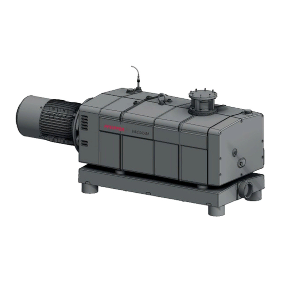
- Page 1 OPERATING INSTRUCTIONS Translation of the Original HEPTA 450 L | 650 L Screw pump...
- Page 2 Dear Customer, Thank you for choosing a Pfeiffer Vacuum product. Your new screw pump is designed to support you with its performance, perfect operation and without impacting your individual application. The name Pfeiffer Vacuum stands for high-quality vacuum technology, a comprehensive and complete range of top-quality products and first-class service.
-
Page 3: Table Of Contents
Table of contents Table of contents About this manual Validity 1.1.1 Applicable documents 1.1.2 Variants Target group Conventions 1.3.1 Instructions in the text 1.3.2 Pictographs 1.3.3 Stickers on the product 1.3.4 Abbreviations Safety General safety information Safety instructions Safety precautions Limits of use of the product Proper use Foreseeable misuse... - Page 4 Decommissioning Decommissioning the vacuum pump Recommissioning Recycling and disposal General disposal information Disposing of the screw pump Malfunctions Service solutions by Pfeiffer Vacuum Accessories 12.1 Accessory information 12.2 Ordering accessories 12.3 Consumables Technical data and dimensions 13.1 General 13.2 Technical data 13.3 Substances in contact with the media...
- Page 5 Tbl. 12: Consumables Tbl. 13: Conversion table: Pressure units Tbl. 14: Conversion table: Units for gas throughput Tbl. 15: Technical data for Hepta 450 L | Hepta 650 L Tbl. 16: Materials that make contact with the process media 5/52...
- Page 6 Filling up lubricant on the vacuum side Fig. 22: Disassembling and cleaning the intake strainer Fig. 23: Cleaning the gas ballast filter Fig. 24: Dimensions of Hepta 450 L Fig. 25: Dimensions of Hepta 650 L (ISO-F DN100) Fig. 26: Hepta 650 L (ISO-F DN160) 6/52...
-
Page 7: About This Manual
Keep the manual for future consultation. 1.1 Validity This operating instructions is a customer document of Pfeiffer Vacuum. The operating instructions de- scribe the functions of the named product and provide the most important information for the safe use of the device. The description is written in accordance with the valid directives. The information in this op- erating instructions refers to the product's current development status. -
Page 8: Pictographs
About this manual 1.3.2 Pictographs The pictographs used in the document indicate useful information. Note true false 1.3.3 Stickers on the product This section describes all the stickers on the product along with their meaning. Rating plate (example) Rating plate for the screw pump Year 2019 D-35614 Asslar... -
Page 9: Abbreviations
About this manual Fig. 1: Position of the stickers on the screw pump 1 Hot surface warning sign Rating plate for the screw pump 2 Arrow indicating direction of rotation 1.3.4 Abbreviations Abbreviation Meaning in this document Operating instructions Fluorocarbon rubber N.N. -
Page 10: Safety
Safety 2 Safety 2.1 General safety information The following 4 risk levels and 1 information level are taken into account in this document. DANGER Immediately pending danger Indicates an immediately pending danger that will result in death or serious injury if not observed. ►... - Page 11 Safety Risks during installation DANGER Danger to life from electric shock Touching exposed and voltage-bearing elements causes an electric shock. Improper connection of the mains supply leads to the risk of touchable live housing parts. There is a risk to life. ►...
- Page 12 Safety WARNING Health hazard through poisoning from toxic contaminated components or devices Toxic process media result in contamination of devices or parts of them. During maintenance work, there is a risk to health from contact with these poisonous substances. Illegal disposal of toxic sub- stances causes environmental damage.
-
Page 13: Safety Precautions
► Observe the unit protection class prior to installation or operation in other environments. ► Provide suitable touch protection, if the surface temperature exceeds 70 °C. 2.4 Limits of use of the product Parameter Hepta 450 L Hepta 650 L Installation location ● Indoors, protected from dust deposits ●... -
Page 14: Proper Use
► Adhere to the installation, commissioning, operating, and maintenance instructions. ► Use only accessory parts recommended by Pfeiffer Vacuum. 2.6 Foreseeable misuse Improper use of the product invalidates all warranty and liability claims. Any use that is counter to the purpose of the product, whether intentional or unintentional, is regarded as misuse, in particular: ●... -
Page 15: Personnel Qualification For Maintenance And Repair
2.7.2 Personnel qualification for maintenance and repair Adequately trained individuals are: ● Maintenance level 1 ─ Customer with technical education ─ Pfeiffer Vacuum service technician ● Maintenance level 3 ─ Pfeiffer Vacuum service technician 15/52... -
Page 16: Product Description
Product description 3 Product description 3.1 Function The HeptaDry screw pumps function according to the double screw-pump principle. Two screw rotors rotate in the compression chamber. The medium to be pumped is trapped between the individual screw coils, compacted and transported to the gas outlet. During the compaction process, the two screw rotors do not come into contact with each other, nor with the suction chamber. -
Page 17: Water Cooling
The silencer reduces the noise level during operation without exhaust line. 3.2 Identifying the product ► To ensure clear identification of the product when communicating with Pfeiffer Vacuum, always keep all of the information on the rating plate to hand. ► Observe the motor-specific data on the motor rating plate attached separately. -
Page 18: Transportation And Storage
► Always transport the screw pump without lubricant. ► Only fill up lubricant at the final installation location. Preparations for transport Pfeiffer Vacuum recommends keeping the transport packaging and original protective cov- General information regarding safe transport 1. Observe the weight specified on packaging. -
Page 19: Storage
5. Always place the vacuum pump on an adequately sized, level surface. 4.2 Storage Storage Pfeiffer Vacuum recommends storing the products in their original transport packaging. Storing the vacuum pump 1. Seal the vacuum and exhaust connection. 2. Make sure that the gas ballast valve is closed. -
Page 20: Installation
NOTICE Property damage from contaminated gases Pumping down gases that contain impurities (condensate, particles) damages the vacuum pump. ► Use suitable filters or separators from the Pfeiffer Vacuum range of accessories, to protect the vacuum pump. NOTICE Property damage from intake of solid particles During commissioning, there is a risk of damage to the suction chamber from dirt from the system or the pipes. -
Page 21: Connecting The Exhaust Side
Pfeiffer Vacuum recommends installing a condensate separator, with condensate drain at the lowest point of the exhaust line. Installation and operation of accessories Pfeiffer Vacuum offers a wide range of specially tailored accessories for your screw pumps. ● Information and ordering options for approved accessories can be found online. -
Page 22: Connecting The Cooling Water Supply
Installation Procedure 1. Remove the protective cap from the exhaust connection. 2. With vertical installation, connect the exhaust line directly with the exhaust connection. 3. With horizontal installation (180°), connect the exhaust line using an outlet elbow. 4. Route the piping downwards from the vacuum pump, to prevent condensate return. 5. -
Page 23: Connecting Sealing Gas
Tbl. 5: Requirements on the cooling water composition Parameter Cooling water Feed capacity Hepta 450 L: 4 ... 10 l/min Hepta 650 L: 6 ... 14 l/min Water pressure 1000 – 6000 hPa Feed temperature +10 – + 30 °C Necessary differential pressure between flow and return flow ≥... -
Page 24: Fill Lubricant
1. Refer to rating plate of the vacuum pump for type and quantity of intended lubricant. 2. Only use the lubricant which was applied during initial installation. – Contact Pfeiffer Vacuum if you want to use another type of lubricant. Required consumable material ●... -
Page 25: Filling Up Lubricant On The Motor Side
Installation 5.6.1 Filling up lubricant on the motor side Fig. 8: Filling up lubricant on the motor side 1 Filler screw Sight glass 2 O-ring Procedure 1. Unscrew the filler screw. 2. Fill up with lubricant according to the marks on the sight glass. 3. -
Page 26: Connect To Mains Power Supply
Installation 5.7 Connect to mains power supply DANGER Danger to life from electric shock Touching exposed and voltage-bearing elements causes an electric shock. Improper connection of the mains supply leads to the risk of touchable live housing parts. There is a risk to life. ►... -
Page 27: Connect Three Phase Motor With 12-Pin Terminal Board
Installation Fig. 10: Delta connection Connect the three phase motor with delta connection ► Connect the three phase motor according to the connection diagram. Fig. 11: Star circuit Connect the three phase motor with star circuit ► Connect the three phase motor according to the connection diagram. 5.7.2 Connect three phase motor with 12-pin terminal board There are 3 circuit arrangements: ●... -
Page 28: Checking The Direction Of Rotation
3. If the direction of rotation is incorrect, exchange the 2 phases of the connecting cable in the motor terminal box. 5.9 Connecting the PTC thermistor tripping unit Tripping units store the shut-down Pfeiffer Vacuum recommends connecting motors with PTC in the stator winding to a PTC resistor tripping device for protection against overload. 28/52... -
Page 29: Fig. 16: Connection Example With Ptc Thermistor Tripping Unit
Installation F1 - F3 AC 220 ... 240 V T1...T3 Fig. 16: Connection example with PTC thermistor tripping unit Control voltage T1 – T3 PTC resistor sensor OFF button Tripping indicator ON button Motor, 3-phase RESET button For devices with two relay outputs only Contactor For MSR type (model) only F1 –... -
Page 30: Operation
NOTICE Property damage from contaminated gases Pumping down gases that contain impurities (condensate, particles) damages the vacuum pump. ► Use suitable filters or separators from the Pfeiffer Vacuum range of accessories, to protect the vacuum pump. Before switching on 1. Inspect the screw pump for visible damage and ensure that the screw pump is only operated when in a sound condition. -
Page 31: Switching Off The Vacuum Pump
Operation NOTICE Damage to the vacuum pump due to intense temperature fluctuations If the housing cools down too quickly due to external influences, there is a risk of contact being made between the rotor at warm operating temperature, and the colder pump housing. This will result in irreversible pump damage. -
Page 32: Maintenance
Maintenance 7 Maintenance 7.1 Maintenance information WARNING Health hazard through poisoning from toxic contaminated components or devices Toxic process media result in contamination of devices or parts of them. During maintenance work, there is a risk to health from contact with these poisonous substances. Illegal disposal of toxic sub- stances causes environmental damage. -
Page 33: Checklist For Inspection And Maintenance
Level 1 and Maintenance Level 3 (revision). If the required intervals listed below are exceeded, or if maintenance work is carried out improperly, no warranty or liability claims are accepted on the part of Pfeiffer Vacuum. This also applies wherever parts other than original spare parts are used. -
Page 34: Checking The Lubricant Level
► Use approved lubricant only. ► Use alternative, application-specific lubricants only following consultation with Pfeiffer Vacuum. Pfeiffer Vacuum recommends determining the precise service life of the lubricant in the first operating year. The usable life may deviate from the reference value specified depending on thermic and chemical loads, or due to penetrating process media in gear and bearing chambers. -
Page 35: Draining Lubricant On The Motor Side
Maintenance Safety data sheets You can obtain the safety data sheets for lubricants from Pfeiffer Vacuum on request, or from the Pfeiffer Vacuum Download Center. The lubricant type is listed on the rating plate 1. Please refer to rating plate of the vacuum pump for type and quantity of intended lubricant. -
Page 36: Draining Lubricant On The Vacuum Side
Maintenance 7.4.2 Draining lubricant on the vacuum side Fig. 19: Draining lubricant on the vacuum side 1 Magnetic sealing plug Collection receptacle 2 Drain screw Procedure 1. Place a collection receptacle beneath the drain hole on the vacuum side. 2. Unscrew the drain screw. 3. -
Page 37: Filling Up Lubricant On The Vacuum Side
Maintenance 7.4.4 Filling up lubricant on the vacuum side Fig. 21: Filling up lubricant on the vacuum side 1 Filler screw Sight glass 2 O-ring Procedure 1. Unscrew the filler screw. 2. Fill up the lubricant as indicated on the sight glass. –... -
Page 38: Cleaning The Gas Ballast Filter
Maintenance Fig. 22: Disassembling and cleaning the intake strainer 1 Interior hexagon socket screw (8x) Compressed air 2 Vacuum flange Intake strainer Disassemble and clean the intake strainer 1. Unscrew the interior hexagon socket screws. 2. Remove the vacuum flange. 3. -
Page 39: Fig. 23: Cleaning The Gas Ballast Filter
Maintenance Fig. 23: Cleaning the gas ballast filter 1 Gas ballast line Compressed air 2 Gas ballast filter Removing and cleaning the gas ballast filter 1. Dismantle the gas ballast filter. 2. Check the gas ballast filter for contamination. 3. Clean the gas ballast filter using compressed air. Installing the gas ballast filter ►... -
Page 40: Decommissioning
► Change the lubricant. ► Replace the bearing and elastomer parts. ► Observe the maintenance instructions. ► Consult Pfeiffer Vacuum if necessary. Procedure when recommissioning the vacuum pump 1. Put the vacuum pump into operation only if it is in a correct state. - Page 41 Decommissioning 3. Screw in the closing screw. 4. Switch the vacuum pump on. 41/52...
-
Page 42: Recycling And Disposal
– Fluoroelastomers (FKM) – Potentially contaminated components that come into contact with media 9.2 Disposing of the screw pump Pfeiffer Vacuum screw pumps from the HeptaDry series contain materials which must be recycled. 1. Fully drain the lubricant. 2. Dismantle the motor. -
Page 43: Malfunctions
► Wear personal protective equipment if necessary. NOTICE Danger of property damage from improper maintenance Unprofessional work on the vacuum pump will lead to damage for which Pfeiffer Vacuum accepts no liability. ► When ordering spare parts, specify the information on the nameplate. -
Page 44: Tbl. 10: Troubleshooting
● Have the seals affected replaced, if necessary. ● If necessary, contact Pfeiffer Vacuum Service. Unusual noises during ● Suction chamber dirty ● Switch off the vacuum pump immedi- operation ately. -
Page 45: Service Solutions By Pfeiffer Vacuum
We are always focused on perfecting our core competence – servicing of vacuum components. Once you have purchased a product from Pfeiffer Vacuum, our service is far from over. This is often exactly where service begins. Obviously, in proven Pfeiffer Vacuum quality. - Page 46 Service solutions by Pfeiffer Vacuum 5. Prepare the product for transport in accordance with the provisions in the contamination declaration. a) Neutralize the product with nitrogen or dry air. b) Seal all openings with blind flanges, so that they are airtight.
-
Page 47: Accessories
Accessories 12 Accessories View the range of accessories for screw pumps on our website. 12.1 Accessory information PTC resistor tripping unit for motor protection Monitors the motor winding temperature Dust separators Protects the pump from particles out of processes 12.2 Ordering accessories Description Order number PTC-resistor tripping device for motor protection 220 –... -
Page 48: Technical Data And Dimensions
Weight 500 kg 700 kg Tbl. 15: Technical data for Hepta 450 L | Hepta 650 L 13.3 Substances in contact with the media Check whether the following materials are chemically resistant to the process media being conveyed. Pump parts Substances in contact with the media... -
Page 49: Dimensions
Substances in contact with the media Inlet/exhaust flange Aluminium Seals Screws Galvanized steel, stainless steel Tbl. 16: Materials that make contact with the process media 13.4 Dimensions Ø 75 4xM12 1266 Fig. 24: Dimensions of Hepta 450 L Dimensions in mm 49/52... -
Page 50: Fig. 25: Dimensions Of Hepta 650 L (Iso-F Dn100)
Technical data and dimensions 602.5 4xM16 324.5 1556.4 754.9 Fig. 25: Dimensions of Hepta 650 L (ISO-F DN100) Dimensions in mm 602.5 4xM16 324.5 1556.4 754.9 Fig. 26: Hepta 650 L (ISO-F DN160) Dimensions in mm 50/52... -
Page 51: Declaration Of Conformity
DIN EN ISO 2151 : 2009-01 DIN EN 13849-1: 2016-06 The authorized representative for the compilation of technical documents is Mr. Wolf- gang Bremer, Pfeiffer Vacuum GmbH, Berliner Straße 43, 35614 Asslar, Germany. Signature: Pfeiffer Vacuum GmbH Berliner Straße 43...
Need help?
Do you have a question about the HEPTA 450 L and is the answer not in the manual?
Questions and answers