
Related Manuals for Pfeiffer Vacuum HEPTA 950 L


Summary of Contents for Pfeiffer Vacuum HEPTA 950 L
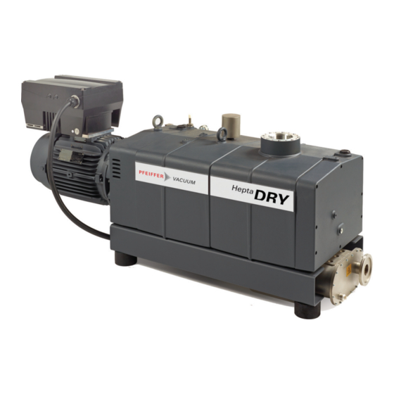
- Page 1 OPERATING INSTRUCTIONS Translation of the Original HEPTA 950 L Screw pump with integrated frequency converter...
- Page 2 Dear Customer, Thank you for choosing a Pfeiffer Vacuum product. Your new screw pump is designed to support you with its performance, perfect operation and without impacting your individual application. The name Pfeiffer Vacuum stands for high-quality vacuum technology, a comprehensive and complete range of top-quality products and first-class service.
-
Page 3: Table Of Contents
Table of contents Table of contents About this manual Validity 1.1.1 Applicable documents 1.1.2 Variants Target group Conventions 1.3.1 Instructions in the text 1.3.2 Pictographs 1.3.3 Stickers on the product 1.3.4 Abbreviations Trademark proof Safety General safety information Safety instructions Safety precautions Limits of use of the product Proper use... - Page 4 Decommissioning Decommissioning the vacuum pump Recommissioning Recycling and disposal General disposal information Disposing of the screw pump Malfunctions Service solutions by Pfeiffer Vacuum Accessories 12.1 Accessory information 12.2 Order accessories 12.3 Consumables Technical data and dimensions 13.1 General 13.2 Technical data 13.3 Substances in contact with the media...
- Page 5 Troubleshooting Tbl. 11: Accessories Tbl. 12: Consumables Tbl. 13: Conversion table: Pressure units Tbl. 14: Conversion table: Units for gas throughput Tbl. 15: Technical data for Hepta 950 L Tbl. 16: Materials that make contact with the process media 5/52...
- Page 6 Fig. 15: Filling lubricant on the motor side Fig. 16: Filling lubricant on the vacuum side Fig. 17: Disassembling and cleaning the intake strainer Fig. 18: Cleaning the gas ballast filter Fig. 19: Dimensions Hepta 950 L | 72 Hz 6/52...
-
Page 7: About This Manual
Keep the manual for future consultation. 1.1 Validity This operating instructions is a customer document of Pfeiffer Vacuum. The operating instructions de- scribe the functions of the named product and provide the most important information for the safe use of the device. The description is written in accordance with the valid directives. The information in this op- erating instructions refers to the product's current development status. -
Page 8: Pictographs
Rating plate for the screw pump 2019 D-35614 Asslar D-35 Made in Germany Vacuum Pump Hepta 950 L S/N = PPPPYYWWNNNN = ≤ 0.05 hPa (mbar) = 950 m³/h = 4320 min m = 1000 kg Oil = Pfeiffer D1... -
Page 9: Abbreviations
About this manual Fig. 1: Position of the stickers on the screw pump 1 Operating instructions note Arrow indicating direction of rotation 2 Sticker with date of lubricant filling Rating plate for the screw pump 3 Hot surface warning sign Hot surface warning sign 4 Rating plate of frequency converter 1.3.4 Abbreviations... -
Page 10: Safety
Safety 2 Safety 2.1 General safety information The following 4 risk levels and 1 information level are taken into account in this document. DANGER Immediately pending danger Indicates an immediately pending danger that will result in death or serious injury if not observed. ►... - Page 11 Safety Risks during installation DANGER Danger to life from electric shock Touching exposed and voltage-bearing elements causes an electric shock. Improper connection of the mains supply leads to the risk of touchable live housing parts. There is a risk to life. ►...
- Page 12 Safety Risks during operation CAUTION Health hazard from increased noise emission Remaining in the close proximity of the vacuum pump for a sustained period of time may cause hear- ing damage. ► Ensure adequate sound insulation. ► Wear hearing protection. CAUTION Danger of burns on hot surfaces Depending on the operating and ambient conditions, the surface temperature of the vacuum pump...
- Page 13 Safety WARNING Danger to life from electric shock in the event of a fault In the event of a fault, devices connected to the mains may be live. There is a danger to life from electric shock when making contact with live components. ►...
-
Page 14: Safety Precautions
(e.g. solvents) are pumped. ► Operate the vacuum pump within the application limits of the product and in compliance with the technical data. ► Adhere to the installation, commissioning, operating, and maintenance instructions. ► Use only accessory parts recommended by Pfeiffer Vacuum. 14/52... -
Page 15: Foreseeable Improper Use
Safety 2.6 Foreseeable improper use Improper use of the product invalidates all warranty and liability claims. Any use that is counter to the purpose of the product, whether intentional or unintentional, is regarded as improper use; in particular: ● Pumping of corrosive media ●... - Page 16 Safety ● Maintenance level 1 ─ Customer with technical education ─ Pfeiffer Vacuum service technician ● Maintenance level 3 ─ Pfeiffer Vacuum service technician 16/52...
-
Page 17: Product Description
Product description 3 Product description 3.1 Function The HeptaDry screw pumps function according to the double screw-pump principle. Two screw rotors rotate in the compression chamber. The medium to be pumped is trapped between the individual screw coils, compacted and transported to the gas outlet. During the compaction process, the two screw rotors do not come into contact with each other, nor with the suction chamber. -
Page 18: Frequency Converter
The silencer reduces the noise level during operation without exhaust line. 3.2 Identifying the product ► To ensure clear identification of the product when communicating with Pfeiffer Vacuum, always keep all of the information on the rating plate to hand. ► Observe the motor-specific data on the motor rating plate attached separately. -
Page 19: Transportation And Storage
► Always transport the screw pump without lubricant. ► Only fill up lubricant at the final installation location. Preparations for transport Pfeiffer Vacuum recommends keeping the transport packaging and original protective cov- General information regarding safe transport 1. Observe the weight specified on packaging. -
Page 20: Bearing
► Connect the screw pump to the mains power supply every 18 months for 60 minutes. Storage Pfeiffer Vacuum recommends storing the products in their original transport packaging. Store the vacuum pump 1. Seal the vacuum and exhaust connection. -
Page 21: Installation
NOTICE Property damage from contaminated gases Pumping gases that contain contamination damages the vacuum pump. ► Use suitable filters or separators from the Pfeiffer Vacuum range of accessories, to protect the vacuum pump. NOTICE Property damage from intake of solid particles During commissioning, there is a risk of damage to the suction chamber from dirt from the system or the pipes. -
Page 22: Connecting Exhaust Side
Pfeiffer Vacuum recommends installing a condensate separator, with condensate drain at the lowest point of the exhaust line. Installation and operation of accessories Pfeiffer Vacuum offers a wide range of specially tailored accessories for your screw pumps. ● Information and ordering options for approved accessories can be found online. -
Page 23: Connecting Cooling Water Supply
Installation Procedure 1. Remove the protective cap from the exhaust connection. 2. With vertical installation, connect the exhaust line directly with the exhaust connection. 3. With horizontal installation (180°), connect the exhaust line using an outlet elbow. 4. Route the piping downwards from the vacuum pump, to prevent condensate return. 5. -
Page 24: Connecting Sealing Gas
Installation Parameter Cooling water Feed capacity 8 – 16 l/min Water pressure 1000 – 6000 hPa Feed temperature 10 – 30 °C Necessary differential pressure between flow and return flow ≥ 1000 Pa Tbl. 6: Prerequisites for the cooling water 5.5 Connecting sealing gas Sealing gas protects against contamination at the points of shaft feedthrough when conveying solvents or reactive gases. -
Page 25: Filling Lubricant
1. Please refer to rating plate of the vacuum pump for type and quantity of intended lubricant. 2. Only use the lubricant which was applied during initial installation. – Contact Pfeiffer Vacuum if you want to use another type of lubricant. Required consumables ●... -
Page 26: Fillin Lubricant On The Vacuum Side
Installation Procedure 1. Unscrew the filler screw. 2. Fill up with lubricant according to the marks on the sight glass. 3. Screw in the filler screw. 4. Check the fill level during operation when running with final pressure. 5.6.2 Fillin lubricant on the vacuum side Fig. - Page 27 ► Route the mains connection in accordance with locally applicable provisions. ► Always provide a suitable mains fuse to protect the motor and supply cable in the event of a fault. – Pfeiffer Vacuum recommends the circuit breaker type "K" with slow tripping characteristic. NOTICE...
-
Page 28: Connecting The Operating Temperature Monitoring
Installation Fig. 10: Connecting power supply to the frequency converter L1 Mains phase 1 Mains phase 3 L2 Mains phase 2 Grounding cable Procedure ► Implement the power connection as described in the associated INVEOR M frequency converter operating instructions. 5.8 Connecting the operating temperature monitoring The thermal circuit breaker monitors the operating temperature of the vacuum pump. -
Page 29: Tbl. 8: Technical Data
Installation Fig. 11: Connecting temperature switch Connection cable, brown Connection cable, black Connection cable, white Thermal circuit breaker (T) Connection cable, blue Procedure 1. Electrically connect the temperature switch as follows: – If the temperature exceeds the switch-point, an alarm is triggered and the vacuum pump switches off. -
Page 30: Operation
NOTICE Property damage from contaminated gases Pumping gases that contain contamination damages the vacuum pump. ► Use suitable filters or separators from the Pfeiffer Vacuum range of accessories, to protect the vacuum pump. Before switching on 1. Inspect the screw pump for visible damage and ensure that the screw pump is only operated when in a sound condition. -
Page 31: Switching Off The Vacuum Pump
Operation NOTICE Damage to the vacuum pump due to intense temperature fluctuations If the housing cools down too quickly due to external influences, there is a risk of contact being made between the rotor at warm operating temperature, and the colder pump housing. This will result in irreversible pump damage. -
Page 32: Maintenance
Maintenance 7 Maintenance 7.1 Maintenance information DANGER Danger to life from electric shock Touching exposed and voltage-bearing elements causes an electric shock. Improper connection of the mains supply leads to the risk of touchable live housing parts. There is a risk to life. ►... -
Page 33: Checklist For Inspection And Maintenance
Level 1 and Maintenance Level 3 (revision). If the required intervals listed below are exceeded, or if maintenance work is carried out improperly, no warranty or liability claims are accepted on the part of Pfeiffer Vacuum. This also applies wherever parts other than original spare parts are used. -
Page 34: Checking The Lubricant Level
Maintenance Action Inspection Maintenance Maintenance Required mate- level 1 level 3 rial described in docu- ment Interval Monthly 8500 h, or once 16000 h or ev- a year at the ery 4 years latest Inspection Visual and acoustic ■ pump check ●... -
Page 35: Changing Lubricant
► Use approved lubricant only. ► Use alternative, application-specific lubricants only following consultation with Pfeiffer Vacuum. Pfeiffer Vacuum recommends determining the precise service life of the lubricant in the first operating year. The usable life may deviate from the reference value specified depending on thermic and chemical loads, or due to penetrating process media in gear and bearing chambers. -
Page 36: Draining Lubricant On The Motor Side
Maintenance Safety data sheets You can obtain the safety data sheets for lubricants from Pfeiffer Vacuum on request, or from the Pfeiffer Vacuum Download Center. The lubricant type is specified on the rating plate 1. Please refer to rating plate of the vacuum pump for type and quantity of intended lubricant. -
Page 37: Draining Lubricant On The Vacuum Side
Maintenance 7.4.2 Draining lubricant on the vacuum side Fig. 14: Draining lubricant on the vacuum side 1 Magnetic sealing plugs Collection receptacle 2 Drain screw Procedure 1. Place a collection receptacle beneath the drain hole on the vacuum side. 2. Unscrew the drain screw. 3. -
Page 38: Fillin Lubricant On The Vacuum Side
Maintenance Procedure 1. Unscrew the filler screw. 2. Fill up with lubricant according to the marks on the sight glass. 3. Screw in the filler screw. 4. Check the fill level during operation when running with final pressure. 7.4.4 Fillin lubricant on the vacuum side Fig. -
Page 39: Cleaning The Gas Ballast Filter
Maintenance Fig. 17: Disassembling and cleaning the intake strainer 1 Interior hexagon socket screw (8x) Compressed air 2 Vacuum flange Intake strainer Disassemble and clean the intake strainer 1. Unscrew the interior hexagon socket screws. 2. Remove the vacuum flange. 3. -
Page 40: Fig. 18: Cleaning The Gas Ballast Filter
Maintenance Fig. 18: Cleaning the gas ballast filter 1 Gas ballast line Compressed air 2 Gas ballast filter Removing and cleaning the gas ballast filter 1. Dismantle the gas ballast filter. 2. Check the gas ballast filter for contamination. 3. Clean the gas ballast filter using compressed air. Installing the gas ballast filter ►... -
Page 41: Decommissioning
► Change the lubricant. ► Replace the bearing and elastomer parts. ► Observe the maintenance instructions. ► Consult Pfeiffer Vacuum if necessary. Procedure when recommissioning the vacuum pump 1. Put the vacuum pump into operation only if it is in a correct state. - Page 42 Decommissioning 3. Screw in the closing screw. 4. Switch the vacuum pump on. 42/52...
-
Page 43: Recycling And Disposal
– Fluoroelastomers (FKM) – Potentially contaminated components that come into contact with media 9.2 Disposing of the screw pump Pfeiffer Vacuum screw pumps from the HeptaDry series contain materials which must be recycled. 1. Fully drain the lubricant. 2. Dismantle the motor. -
Page 44: Malfunctions
► Wear personal protective equipment if necessary. NOTICE Danger of property damage from improper maintenance Unprofessional work on the vacuum pump will lead to damage for which Pfeiffer Vacuum accepts no liability. ► When ordering spare parts, specify the information on the nameplate. -
Page 45: Tbl. 10: Troubleshooting
● Have the seals affected replaced, if necessary. ● If necessary, contact Pfeiffer Vacuum Service. Unusual noises during ● Suction chamber dirty ● Switch off the vacuum pump immedi- operation ately. -
Page 46: Service Solutions By Pfeiffer Vacuum
We are always focused on perfecting our core competence – servicing of vacuum components. Once you have purchased a product from Pfeiffer Vacuum, our service is far from over. This is often exactly where service begins. Obviously, in proven Pfeiffer Vacuum quality. - Page 47 Service solutions by Pfeiffer Vacuum 5. Prepare the product for transport in accordance with the provisions in the contamination declaration. a) Neutralize the product with nitrogen or dry air. b) Seal all openings with blind flanges, so that they are airtight.
-
Page 48: Accessories
12.2 Order accessories Description Part number SAS 100, DN 100 ISO-K, polyester filter PK Z60 512 Check valve Hepta 950 L PU 000 077-T Tbl. 11: Accessories 12.3 Consumables When selecting the type and amount of lubricant, always refer to the specifications on the rating plate. -
Page 49: Technical Data And Dimensions
59.8 0.76 atm cm Tbl. 14: Conversion table: Units for gas throughput 13.2 Technical data Type designation Hepta 950 L Part number PU V72 0007 011 Connection flange (in) DN 100 ISO-K Connection flange (out) DN 100 ISO-K Pumping speed, min. -
Page 50: Substances In Contact With The Media
Screws Galvanized steel, stainless steel Tbl. 16: Materials that make contact with the process media 13.4 Dimensions Ø100 4 x M12 1672 A ( 1 : 5 ) Fig. 19: Dimensions Hepta 950 L | 72 Hz Dimensions in mm 50/52... -
Page 51: Declaration Of Conformity
EN 1012-2: 2011-12 EN 13849-1: 2016-06 DIN EN ISO 2151: 2009-01 The authorized representative for the compilation of technical documents is Mr. Wolf- gang Bremer, Pfeiffer Vacuum GmbH, Berliner Straße 43, 35614 Asslar, Germany. Signature: Pfeiffer Vacuum GmbH Berliner Straße 43...
Need help?
Do you have a question about the HEPTA 950 L and is the answer not in the manual?
Questions and answers