Sign In
Upload
Manuals
Brands
Pfeiffer Vacuum Manuals
Water Pump
HEPTA 400 P
Pfeiffer Vacuum HEPTA 400 P Manuals
Manuals and User Guides for Pfeiffer Vacuum HEPTA 400 P. We have
2
Pfeiffer Vacuum HEPTA 400 P manuals available for free PDF download: Operating Instructions Manual
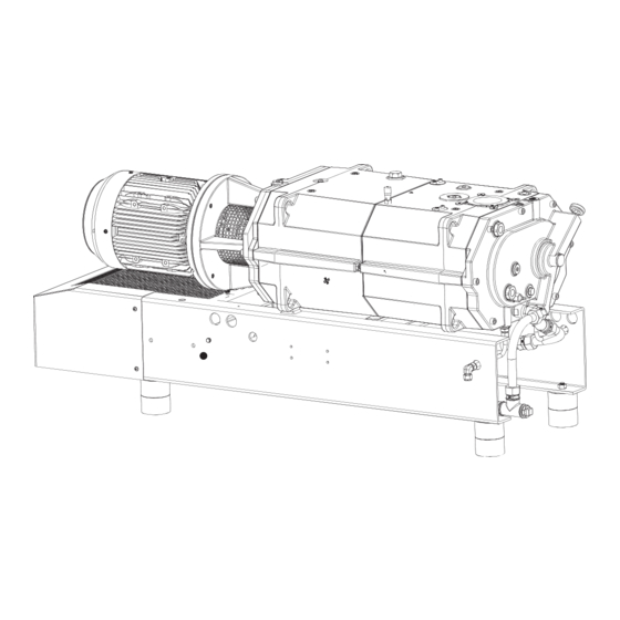
Pfeiffer Vacuum HEPTA 400 P Operating Instructions Manual (140 pages)
Screw pump
Brand:
Pfeiffer Vacuum
| Category:
Water Pump
| Size: 29 MB
Table of Contents
Deutsch
3
Table of Contents
3
Zu dieser Anleitung
7
Gültigkeit
7
Mitgeltende Dokumente
7
Varianten
7
Zielgruppe
7
Konventionen
7
Anweisungen IM Text
7
Aufkleber auf dem Produkt
8
Piktogramme
8
Abkürzungen
9
Markennachweis
9
Abb. 1: Positionsbeispiel der Aufkleber auf dem Produkt
9
Sicherheit
10
Allgemeine Sicherheitshinweise
10
Sicherheitshinweise
10
Sicherheitsmaßnahmen
13
Einsatzgrenzen des Produkts
13
Personenqualifikation Sicherstellen
14
Vorhersehbarer Fehlgebrauch
14
Personenqualifikation
14
Bestimmungsgemäße Verwendung
14
Personenqualifikation bei Wartung und Reparatur
15
Produktbeschreibung
16
Funktion
16
Abb. 2: Funktionsprinzip mit Wärmetauscher
16
Abb. 3: Aufbau der Vakuumpumpe am Beispiel der Hepta 200 | 300 P
16
Sperrgassystem
17
Produktmerkmale
17
Produkt Identifizieren
17
Thermometer
17
Gasballast
17
Wellenabdichtung auf Motor- und Vakuumseite
17
Temperaturüberwachung
17
Wasserkühlung
17
Lieferumfang
18
Transport und Lagerung
19
Transport
19
Lagerung
20
Abb. 4: Vakuumpumpe Transportieren
20
Installation
21
Vakuumpumpe Aufstellen
21
Vakuumseite Anschließen
21
Auspuffseite Anschließen
22
Kühlwasserversorgung Anschließen
23
Abb. 5: Kühlwasseranschluss mit Plattenwärmetauscher
23
Sperrgassystem Anschließen
24
Abb. 6: Sperrgassystem Anschließen
24
Abb. 7: Anschlussdaten für den Durchflusswächter
24
Gasballastsystem Anschließen
25
Abb. 8: Gasballastsystem Anschließen
25
Spülgassystem Anschließen
26
Abb. 9: Anschlussdaten für das Magnetventil
26
Abb. 10: Spülgassystem Anschließen
26
Abb. 11: Anschlussdaten für das Magnetventil
26
Abb. 12: Kupplung Montieren
27
Kühlflüssigkeit Einfüllen
27
Kupplung Montieren
27
Kühlflüssigkeit Einfüllen bei der Hepta 100 P
28
Abb. 13: Kühlflüssigkeit bei Hepta 100 P Einfüllen
28
Kühlflüssigkeit Einfüllen bei Hepta 200 P | 300 P
29
Schmiermittel Einfüllen
29
Abb. 14: Kühlflüssigkeit bei Hepta 200 P | 300 P Einfüllen
29
1Schmiermittel auf der Motorseite Einfüllen
30
Abb. 15: Schmiermittel Einfüllen
30
Abb. 16: Schmiermittel auf der Vakuumseite Einfüllen
31
Netzanschluss Herstellen
31
2Schmiermittel auf der Vakuumseite Einfüllen
31
1Dreiphasenmotor mit 6-Poliger Klemmenplatte Anschließen
32
Abb. 17: Dreieckschaltung
32
2Dreiphasenmotor mit 9-Poliger Klemmenplatte Anschließen
33
3Dreiphasenmotor mit 12-Poliger Klemmenplatte Anschließen
33
Abb. 18: Sternschaltung
33
Abb. 19: Klemmplatte für Niedrige Spannung
33
Abb. 20: Motorwicklung und Klemmplatte für Hohe Spannung
33
Abb. 23: Sternschaltung
34
Abb. 22: Dreieckschaltung
34
Abb. 21: Doppelsternschaltung
34
Drehrichtung Prüfen
34
Kaltleiterauslösegerät Anschließen
35
Abb. 24: Drehrichtung Prüfen
35
Betriebstemperaturüberwachung Anschließen
36
Abb. 25: Anschlussbeispiel mit Kaltleiterauslösegerät
36
Abb. 26: Betriebstemperaturschalter
36
Betrieb
38
Vakuumpumpe in Betrieb Nehmen
38
Kondensierbare Dämpfe Fördern
39
Vakuumpumpe Einschalten
39
Schraubenpumpe mit Flüssigkeit Spülen
40
Schraubenpumpe mit Gas Spülen
40
Abb. 27: Gasballastventil
40
Vakuumpumpe Ausschalten
41
Wartung
42
Wartungsinformationen
42
Checkliste für Inspektion und Wartung
43
Abb. 28: Schmiermittelstand an der Motorseite Kontrollieren
44
Abb. 29: Schmiermittelstand an der Vakuumseite Kontrollieren
44
Schmiermittelstand Kontrollieren
44
Vorgehen bei der Hepta 100 P
44
Kühlflüssigkeitsniveau Kontrollieren
44
Vorgehen bei der Hepta 200 P | 300 P
45
Schmiermittel Wechseln
45
Abb. 30: Kühlflüssigkeitsniveau Kontrollieren
45
Abb. 31: Kühlflüssigkeitsniveau Kontrollieren
45
Schmiermittel auf der Motorseite Ablassen
47
Schmiermittel auf der Vakuumseite Ablassen
47
Abb. 32: Schmiermittel auf der Motorseite Ablassen
47
Abb. 33: Schmiermittel auf der Vakuumseite Ablassen
47
Schmiermittel auf Motorseite Einfüllen
48
Abb. 34: Schmiermittel auf Motorseite Einfüllen
48
Schmiermittel auf der Vakuumseite Einfüllen
49
Kühlflüssigkeit Wechseln
49
Abb. 35: Schmiermittel auf der Vakuumseite Einfüllen
49
Abb. 37: Kühlflüssigkeit Ablassen
50
Abb. 36: Kühlflüssigkeit Ablassen
50
Kühlflüssigkeit Ablassen bei der Hepta 200 | 300 P
50
Kühlflüssigkeit Ablassen bei der Hepta 100 P
50
Kühlflüssigkeit Einfüllen bei der Hepta 100 P
51
Abb. 38: Kühlflüssigkeit bei Hepta 100 P Einfüllen
51
Kühlflüssigkeit Einfüllen bei Hepta 200 P | 300 P
52
Abb. 39: Kühlflüssigkeit bei Hepta 200 P | 300 P Einfüllen
52
Außerbetriebnahme
53
Vakuumpumpe Außer Betrieb Nehmen
53
Wiederinbetriebnahme
53
Schraubenpumpe Entsorgen
55
Recycling und Entsorgung
55
Allgemeine Entsorgungshinweise
55
Störungen
56
Servicelösungen von Pfeiffer Vacuum
58
Zubehör
60
Zubehörinformationen
60
Zubehör Bestellen
60
Verbrauchsmaterialien
60
Technische Daten
61
Allgemeines
61
Medienberührende Werkstoffe
61
Technische Daten und Abmessungen
61
Abmessungen
64
Abb. 40: Abmessungen Hepta 100 P | 50 Hz
64
Abb. 41: Abmessungen Hepta 100 P | 60 Hz
65
Abb. 42: Abmessungen Hepta 200 P | 50 Hz
66
Abb. 43: Abmessungen Hepta 200 P | 60 Hz
66
Abb. 44: Abmessungen Hepta 300 P | 50 Hz
67
Abb. 45: Abmessungen Hepta 300 P | 60 Hz
68
EG Konformitätserklärung
69
Konformitätserklärung
70
English
71
About this Manual
75
Applicable Documents
75
Conventions
75
Instructions in the Text
75
Target Group
75
Validity
75
Variants
75
Pictographs
76
Stickers on the Product
76
Tbl. 1: Stickers on the Product
76
Abbreviations
77
Fig. 1: Position of Sticker on the Product Shown as an Example
77
Tbl. 2: Abbreviations Used in this Document
77
Trademark Proof
77
General Safety Information
78
Safety
78
Safety Instructions
78
Limits of Use of the Product
81
Safety Precautions
81
Ensuring Personnel Qualification
82
Foreseeable Improper Use
82
Personnel Qualification
82
Proper Use
82
Tbl. 3: Limits of Use of the Product
82
Personnel Qualification for Maintenance and Repair
83
Fig. 2: Functional Principle with Heat Exchanger
84
Fig. 3: Structure of the Vacuum Pump Shown on the Hepta 200 | 300 P as an Exam
84
Function
84
Product Description
84
Gas Ballast
85
Identifying the Product
85
Product Features
85
Sealing Gas System
85
Shaft Seal on Motor Side and Vacuum Side
85
Temperature Monitoring
85
Thermometer
85
Water Cooling
85
Scope of Delivery
86
Transport
87
Transportation and Storage
87
Bearing
88
Fig. 4: Transporting the Vacuum Pump
88
Connecting the Vacuum Side
89
Installation
89
Setting up the Vacuum Pump
89
Connecting the Exhaust Side
90
Tbl. 5: Maximum Permissible Forces on the Intake Flange
90
Connecting the Cooling Water Supply
91
Fig. 5: Cooling Water Connection with Plate Heat Exchanger
91
Connecting the Sealing Gas System
92
Fig. 6: Connecting the Sealing Gas System
92
Fig. 7: Connection Data for the Flow Rate Monitor
92
Tbl. 6: Requirements on the Cooling Water Composition
92
Tbl. 7: Contact and Switch-Point According to Sealing System
92
Connecting the Gas Ballast System
93
Fig. 8: Connecting the Gas Ballast System
93
Fig. 9: Connection Data for the Solenoid Valve
93
Tbl. 8: Contact and Switch-Point for Pressure Switch
93
Tbl. 9: Requirements for the Sealing Gas Supply
93
Connecting the Flushing Gas System
94
Fig. 10: Connecting the Flushing Gas System
94
Fig. 11: Connection Data for the Solenoid Valve
94
Tbl. 10: Requirements for the Ballast Gas
94
Tbl. 11: Requirements for the Flushing Gas
94
Fig. 12: Installing the Coupling
95
Filling the Cooling Liquid
95
Installing the Coupling
95
Fig. 13: Filling up the Cooling Liquid on Hepta 100 P
96
Filling up the Cooling Liquid on the Hepta 100 P
96
Fig. 14: Filling up the Cooling Liquid on Hepta 200 P | 300 P
97
Filling up the Cooling Liquid on the Hepta 200 P | 300 P
97
Filling with Lubricant
97
1Filling up Lubricant on the Motor Side
98
Fig. 15: Filling with Lubricant
98
2Filling Lubricant on the Vacuum Side
99
Connect to Mains Power Supply
99
Fig. 16: Filling Lubricant on the Vacuum Side
99
1Connect Three Phase Motor with 6-Pin Terminal Board
100
Fig. 17: Delta Connection
100
2Connect Three Phase Motor with 9-Pin Terminal Board
101
3Connect Three Phase Motor with 12-Pin Terminal Board
101
Fig. 18: Star Circuit
101
Fig. 19: Terminal Board for Low Voltage
101
Fig. 20: Motor Winding and Terminal Board for High Voltage
101
Checking the Direction of Rotation
102
Fig. 21: Double Star Circuit
102
Fig. 22: Delta Connection
102
Fig. 23: Star Circuit
102
Connecting the PTC Thermistor Tripping Unit
103
Fig. 24: Checking the Direction of Rotation
103
Connecting Operating Temperature Monitoring
104
Fig. 25: Connection Example with PTC Thermistor Tripping Unit
104
Fig. 26: Operating Temperature Thermal Circuit Breaker
104
Tbl. 12: Technical Data
105
Commissioning the Vacuum Pump
106
Operation
106
Switching on the Vacuum Pump
106
Conveying Condensable Vapors
107
Fig. 27: Gas Ballast Valve
107
Flushing the Screw Pump with Fluid
108
Flushing the Screw Pump with Gas
108
Switching off the Vacuum Pump
108
Maintenance
109
Maintenance Information
109
Checking the Lubricant Level
110
Checklist for Inspection and Maintenance
110
Tbl. 13: Maintenance Intervals
110
Approach for the Hepta 100 P
111
Checking the Cooling Liquid Level
111
Fig. 28: Checking the Lubricant Level on the Motor Side
111
Fig. 29: Checking the Lubricant Level on the Vacuum Side
111
Fig. 30: Checking the Cooling Liquid Level
111
Approach for the Hepta 200 P | 300 P
112
Changing the Lubricant
112
Fig. 31: Checking the Cooling Liquid Level
112
Draining Lubricant on the Motor Side
113
Fig. 32: Draining Lubricant on the Motor Side
113
Draining Lubricant on the Vacuum Side
114
Fig. 33: Draining Lubricant on the Vacuum Side
114
Fig. 34: Filling Lubricant on the Motor Side
115
Fig. 35: Filling Lubricant on the Vacuum Side
115
Filling Lubricant on the Motor Side
115
Filling Lubricant on the Vacuum Side
115
Changing the Cooling Liquid
116
Draining the Cooling Liquid on the Hepta 100 P
116
Fig. 36: Draining the Cooling Liquid
116
Draining the Cooling Liquid on the Hepta 200 | 300 P
117
Fig. 37: Draining the Cooling Liquid
117
Fig. 38: Filling up the Cooling Liquid on Hepta 100 P
118
Filling up the Cooling Liquid on the Hepta 100 P
118
Fig. 39: Filling up the Cooling Liquid on Hepta 200 P | 300 P
119
Filling up the Cooling Liquid on the Hepta 200 P | 300 P
119
Decommissioning
120
Decommissioning the Vacuum Pump
120
Recommissioning
120
Disposing of the Screw Pump
122
General Disposal Information
122
Recycling and Disposal
122
Malfunctions
123
Tbl. 14: Troubleshooting
124
Service Solutions by Pfeiffer Vacuum
125
Accessories
127
Accessory Information
127
Consumables
127
Ordering Accessories
127
Tbl. 15: Accessories
127
Tbl. 16: Consumables
127
General
128
Substances in Contact with the Media
128
Technical Data
128
Technical Data and Dimensions
128
Tbl. 20: Technical Data for Hepta 100 P
129
Tbl. 21: Technical Data for Hepta 200 P
129
Tbl. 22: Technical Data for Hepta 300 P
130
Dimensions
131
Fig. 40: Dimensions of Hepta 100 P | 50 Hz
131
Fig. 41: Dimensions of Hepta 100 P | 60 Hz
132
Fig. 42: Dimensions of Hepta 200 P | 50 Hz
133
Fig. 43: Dimensions of Hepta 200 P | 60 Hz
133
Fig. 44: Dimensions of Hepta 300 P | 50 Hz
134
Fig. 45: Dimensions of Hepta 300 P | 60 Hz
135
EC Declaration of Conformity
136
Declaration of Conformity
137
Advertisement
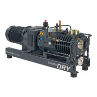
Pfeiffer Vacuum HEPTA 400 P Operating Instructions Manual (64 pages)
Screw pump
Brand:
Pfeiffer Vacuum
| Category:
Water Pump
| Size: 16 MB
Table of Contents
Table of Contents
3
About this Manual
7
Validity
7
Applicable Documents
7
Variants
7
Target Group
7
Conventions
7
Instructions in the Text
7
Pictographs
8
Stickers on the Product
8
Tbl. 1: Stickers on the Product
8
Fig. 1: Position of Sticker on the Product Shown as an Example
8
Abbreviations
9
Trademark Proof
9
Tbl. 2: Abbreviations Used in this Document
9
Safety
10
General Safety Information
10
Safety Instructions
10
Safety Precautions
13
Limits of Use of the Product
13
Proper Use
14
Foreseeable Improper Use
14
Personnel Qualification
14
Ensuring Personnel Qualification
14
Tbl. 3: Limits of Use of the Product
14
Personnel Qualification for Maintenance and Repair
15
Product Description
16
Function
16
Air Cooling
16
Fig. 2: Operating Principle
16
Fig. 3: Structure of the Vacuum Pump
16
Temperature Monitoring
17
Thermometer
17
Shaft Seal on Motor Side and Vacuum Side
17
Gas Ballast
17
Sealing Gas System
17
Safety Valve
17
Non-Return Valve
17
Identifying the Product
17
Product Features
17
Scope of Delivery
17
Transportation and Storage
18
Transport
18
Fig. 4: Transporting the Vacuum Pump
18
Bearing
19
Installation
20
Setting up the Vacuum Pump
20
Connecting the Vacuum Side
20
Fig. 5: Setting up the Vacuum Pump
20
Tbl. 5: Maximum Permissible Forces on the Intake Flange
21
Connecting the Exhaust Side
22
Connecting the Sealing Gas System
22
Fig. 6: Connecting the Sealing Gas System
23
Fig. 7: Connecting the Sealing Gas System with Nitrogen Monitoring Tablet
23
Fig. 8: Connection Data for the Solenoid Valve
23
Connecting the Gas Ballast System
24
Tbl. 6: Requirements for the Sealing Gas
24
Fig. 9: Connection Data for the Flow Rate Monitor
24
Fig. 10: Connecting the Gas Ballast System
24
Fig. 11: Connection Data for the Solenoid Valve
24
Connecting the Flushing Gas System
25
Tbl. 7: Requirements for the Ballast Gas
25
Fig. 12: Connecting the Flushing Gas System
25
Fig. 13: Connection Data for the Solenoid Valve
25
Installing the Coupling
26
Connecting the Silencer
26
Tbl. 8: Requirements for the Flushing Gas
26
Fig. 14: Installing the Coupling
26
Filling the Cooling Liquid
27
Fig. 15: Connecting the Silencer
27
Filling with Lubricant
28
Fig. 16: Filling the Cooling Liquid
28
1Filling Lubricant on the Motor Side
29
2Filling Lubricant on the Vacuum Side
29
Fig. 17: Filling Lubricant on the Motor Side
29
Fig. 18: Filling Lubricant on the Vacuum Side
29
Connect to Mains Power Supply
30
1Connect Three Phase Motor with 6-Pin Terminal Board
31
2Connect Three Phase Motor with 12-Pin Terminal Board
31
Fig. 19: Delta Connection
31
Fig. 20: Star Circuit
31
Fig. 21: Double Star Circuit
31
Checking the Direction of Rotation
32
Fig. 22: Delta Connection
32
Fig. 23: Star Circuit
32
Fig. 24: Checking the Direction of Rotation
32
Connecting the Water/Air Heat Exchanger
33
Fig. 25: Direction of Air Flow
33
Fig. 26: Connection Data for the 24 V Fan Motor
33
Connecting the PTC Thermistor Tripping Unit
34
Fig. 27: Delta Connection
34
Fig. 28: Star Circuit
34
Fig. 29: Connection Example with PTC Thermistor Tripping Unit
35
Operation
36
Commissioning the Vacuum Pump
36
Switching on the Vacuum Pump
37
Conveying Condensable Vapors
37
Fig. 30: Gas Ballast Valve
37
Flushing the Screw Pump with Fluid
38
Flushing the Screw Pump with Gas
38
Switching off the Vacuum Pump
38
Maintenance
40
Maintenance Information
40
Checklist for Inspection and Maintenance
41
Checking the Lubricant Level
41
Tbl. 9: Maintenance Intervals
41
Checking the Cooling Liquid Level
42
Changing the Lubricant
42
Fig. 31: Checking the Lubricant Level on the Motor Side
42
Fig. 32: Checking the Lubricant Level on the Vacuum Side
42
Fig. 33: Checking the Cooling Liquid Level
42
Draining Lubricant on the Motor Side
44
Draining Lubricant on the Vacuum Side
44
Fig. 34: Draining Lubricant on the Motor Side
44
Fig. 35: Draining Lubricant on the Vacuum Side
44
Filling Lubricant on the Motor Side
45
Filling Lubricant on the Vacuum Side
45
Fig. 36: Filling Lubricant on the Motor Side
45
Fig. 37: Filling Lubricant on the Vacuum Side
45
Changing the Cooling Liquid
46
Draining the Cooling Liquid
46
Fig. 38: Draining the Cooling Liquid
46
Filling the Cooling Liquid
47
Fig. 39: Filling the Cooling Liquid
47
Changing the Gas Ballast Filter
48
Draining the Condensate in the Silencer
48
Fig. 40: Changing the Gas Ballast Filter
48
Decommissioning
50
Decommissioning the Vacuum Pump
50
Recommissioning
50
Recycling and Disposal
52
General Disposal Information
52
Disposing of the Screw Pump
52
Malfunctions
53
Tbl. 10: Troubleshooting
54
Service Solutions by Pfeiffer Vacuum
55
Accessories
57
Accessory Information
57
Ordering Accessories
57
Consumables
57
Technical Data and Dimensions
58
General
58
Technical Data
58
Substances in Contact with the Media
58
Tbl. 13: Conversion Table: Pressure Units
58
Tbl. 14: Conversion Table: Units for Gas Throughput
58
Tbl. 15: Technical Data for Hepta 400 P
58
Dimensions
59
Tbl. 16: Materials that Make Contact with the Process Media
59
Fig. 41: Dimensions of Hepta 400 P
59
EC Declaration of Conformity
60
Declaration of Conformity
61
Advertisement
Related Products
Pfeiffer Vacuum HEPTA 630 P
Pfeiffer Vacuum HEPTA 100 P
Pfeiffer Vacuum HEPTA 200 P
Pfeiffer Vacuum HEPTA 300 P
Pfeiffer Vacuum HEPTA 950 L
Pfeiffer Vacuum HEPTA 450 L
Pfeiffer Vacuum HEPTA 650 L
Pfeiffer Vacuum HENA 302 K
Pfeiffer Vacuum HENA 50
Pfeiffer Vacuum HENA 301
Pfeiffer Vacuum Categories
Water Pump
Control Unit
Measuring Instruments
Industrial Equipment
Security Sensors
More Pfeiffer Vacuum Manuals
Login
Sign In
OR
Sign in with Facebook
Sign in with Google
Upload manual
Upload from disk
Upload from URL