Table of Contents
Advertisement
Quick Links
AT32-Video-EV User Manual
AT32-Video-EV board
Introduction
The AT32-Video-EV evaluation board is designed to achieve faster data acquisition and application
through video sensor, thus speeding up development cycles.
The evaluation board is built around a QVGA CMOS image sensor — BF3901 (BYD brand), and a
TM
2.4-inch TFT LCD touch display. Standard Arduino
Uno R3 connectors are intended for
connection to the ARTERY AT-START evaluation board or other compatible boards. Through
image processing control mechanism, the AT32-Video-EV board is aiming at driving various
applications such as QR code scanning, image recognition and gesture control.
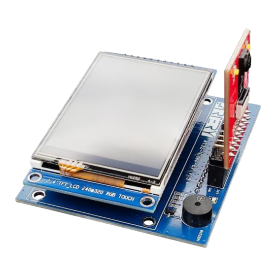
Figure 1. AT32-Video-EV board outlook
2022.9.13
1
Rev 1.30
Advertisement
Table of Contents

Related Manuals for ARTERY AT32-Video-EV


Summary of Contents for ARTERY AT32-Video-EV
-
Page 1: Figure 1. At32-Video-Ev Board Outlook
AT32-Video-EV board Introduction The AT32-Video-EV evaluation board is designed to achieve faster data acquisition and application through video sensor, thus speeding up development cycles. The evaluation board is built around a QVGA CMOS image sensor — BF3901 (BYD brand), and a 2.4-inch TFT LCD touch display. -
Page 2: Table Of Contents
AT32-Video-EV User Manual Contents Hardware layout and configuration ..............5 Arduino connectors ....................8 How to use AT32-Video-EV ................. 10 Schematics ......................11 Revision history ....................13 2022.9.13 Rev 1.30... - Page 3 AT32-Video-EV User Manual List of tables Table 1. Arduino Uno R3 connectors definition ................8 Table 2. Document Document revision history .................. 13 2022.9.13 Rev 1.30...
- Page 4 Figure 5. BF3901 camera module board top view ................7 Figure 6. BF3901 camera module board bottom layout ..............7 Figure 7. AT32-Video-EV combined with AT-START-F403A............. 10 Figure 8. Schematic diagram of Arduino connecting board .............. 11 Figure 9. Schematic diagram of BF3901 camera module board ............12 2022.9.13...
-
Page 5: Hardware Layout And Configuration
AT32-Video-EV User Manual Hardware layout and configuration The AT32-Video-EV evaluation board consists of an Arduino connectors board (blue) and a BF3901 camera module board (red). The video evaluation board can be linked to the AT-START evaluation board through Arduino connectors. The microcontroller on the AT-START evaluation board acquires images from the BF3901CS sensor via SPI bus. -
Page 6: Figure 3. Arduino Connectors Board Top View
AT32-Video-EV User Manual Figure 3. Arduino connectors board top view GPIO LED Camera module connector Buzzer LCD touch display connector Figure 4. Arduino connectors board bottom view Arduino Uno extension connector Arduino Uno extension connector Arduino Uno extension connector 2022.9.13... -
Page 7: Figure 5. Bf3901 Camera Module Board Top View
AT32-Video-EV User Manual Figure 5. BF3901 camera module board top view White LED BF3901 camera Camera module connector Figure 6. BF3901 camera module board bottom layout 2022.9.13 Rev 1.30... -
Page 8: Arduino Connectors
AT32-Video-EV User Manual Arduino connectors Table 1. Arduino Uno R3 connectors definition Arduino AT32F403A Connector Function Description pin name pin name IOREF 3.3 V reference RESET NRST External reset Power supply for LCD screen and 3.3V 3.3 V input/output input for voltage regulator on camera... - Page 9 AT32-Video-EV User Manual Arduino AT32F403A Connector Function Description pin name pin name SPI2_MISO is connected to HREF/D2 MISO PB14 SPI2_MISO on image sensor 5 V input/output SPI2_SCK is connected to VCLK on PB13 SPI2_SCK image sensor SPI2_MOSI is connected to D0 on...
-
Page 10: How To Use At32-Video-Ev
AT32-Video-EV User Manual How to use AT32-Video-EV Connect the Arduino connectors board on AT32-Video-EV board to the BF3901 camera module board, and interface the combined board with the AT-START board through Arduino connectors (following the connectors arrangement) during which the camera should face forward. After successful connection, the final PCB board can be provided with 5 V and 3.3 V power (refer to the... -
Page 11: Schematics
AT32-Video-EV User Manual Schematics Figure 8. Schematic diagram of Arduino connecting board BUZZER1 R1 33Ω HNB09A05 R2 1K PB0/BUZZ S8050 PB8/CAMERA_PD PB9/CAMERA_LED R4 1K LED1 PB4/GREEN PA5/SPI1_SCK Green PA6/SPI1_MISO PA7/SPI1_MOSI PA15/LCD_RST PC7/LCD_DC PA9/LCD_BLK 2.54mm 1x10P 2.54mm 1x8P PA8/MCLK PA5/SPI1_SCK PB10/CAMERA_SCL... -
Page 12: Figure 9. Schematic Diagram Of Bf3901 Camera Module Board
AT32-Video-EV User Manual Figure 9. Schematic diagram of BF3901 camera module board D0VDD 100Ω@100MHz AVDD 2.85V LED1 LED2 10uF 100nF 10uF 100nF 100nF 100nF White White LP5907MFX-2.8/NOPB 33Ω R2 1K LED_CTRL S8050 D0VDD D0VDD Tri-state OSC/MCLK OUTPUT 100nF NC(24MHz) D0VDD 4.7K... -
Page 13: Revision History
AT32-Video-EV User Manual Revision history Table 2. Document revision history Date Revision Changes 2018.7.26 Initial release 1. Changed the revision code of this document to three-digital format. The first two digital refers to hardware version, and the last digital refers to 2018.8.24... - Page 14 No license, express or implied, to any intellectual property rights is granted under this document. If any part of this document deals with any third party products or services, it shall not be deemed a license grant by ARTERY for the use of such third party products or services, or any intellectual property contained therein, or considered as a warranty regarding the use in any manner whatsoever of such third party products or services or any intellectual property contained therein.
Need help?
Do you have a question about the AT32-Video-EV and is the answer not in the manual?
Questions and answers