Table of Contents
Advertisement
Quick Links
AT-START-F407 User Manual
Get started with AT32F407VGT7
Introduction
AT-START-F407 is designed to help you explore the high-performance features of the 32-bit
®
microcontroller, AT32F407 embedded with ARM Cortex
-M4F with FPU, and help develop your
applications.
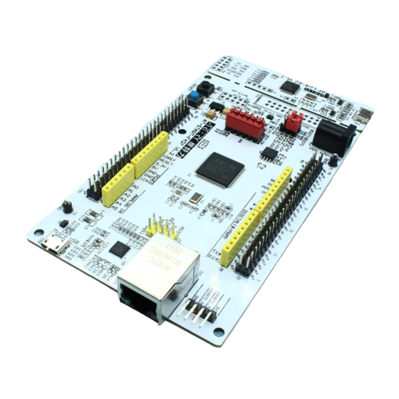
AT-START-F407 is an evaluation board based on AT32F407VGT7 chip with LED indicators,
TM
buttons, an USB micro-B connector, an Ethernet RJ45 connector, Arduino
Uno R3 extension
connector and an expanded 16 MB SPI Flash memory. This evaluation board embeds
debugging/programming tool AT-Link-EZ without the need of other development tools.
2020.11.20
1
Rev 1.20
www.arterytek.com
Advertisement
Table of Contents

Related Manuals for ARTERY AT-START-F407


Summary of Contents for ARTERY AT-START-F407
- Page 1 AT-START-F407 User Manual Get started with AT32F407VGT7 Introduction AT-START-F407 is designed to help you explore the high-performance features of the 32-bit ® microcontroller, AT32F407 embedded with ARM Cortex -M4F with FPU, and help develop your applications. AT-START-F407 is an evaluation board based on AT32F407VGT7 chip with LED indicators,...
-
Page 2: Table Of Contents
Overview ......................... 5 Features ........................5 Definition of terms ....................5 Quick start ......................6 Get started........................ 6 Toolchains supporting AT-START-F407 ..............6 Hardware and layout ..................... 7 Power supply selection ..................... 9 IDD ........................... 9 Programming and debugging ................. 10 3.3.1... - Page 3 AT-START-F407 User Manual List of tables Table 1. Boot mode selection jumper setting ..................11 Table 2. GPIO and SPIM jumper setting.................... 12 Table 3. 0 Ω resistor setting ....................... 14 Table 4. Arduino Uno R3 extension connector pin definition ............15 Table 5.
- Page 4 AT-START-F407 User Manual List of figures Figure 1. Hardware block diagram ...................... 7 Figure 2. Top layer ..........................8 Figure 3. Bottom layer ......................... 8 Figure 4. Schematic (AT-Link-EZ) ..................... 17 Figure 5. Schematic (microcontroller) ....................18 Figure 6. Schematic (power supply and peripherals) ................ 19 Figure 7.
-
Page 5: Overview
− The on-board AT-Link-EZ can be used for programming and debugging (AT-Link-EZ is a simplified version of AT-Link, and does not support offline mode) − If AT-Link-EZ is separated from this board by bending over along the joint, AT-START-F407 can be connected to an independent AT-Link for programming and debugging ... -
Page 6: Quick Start
JP8 one-piece jumper is connected to the I/O on the right. 2. Connect the AT-START-F407 board to the PC through an USB cable (Type A to micro-B), and the board will be powered via AT-Link-EZ USB connector CN6. LED1 (red) is always on, and the other three LEDs (LED2 to LED4) start to blink in turn. -
Page 7: Hardware And Layout
AT-START-F407 User Manual Hardware and layout AT-START-F407 board is designed around an AT32F407VGT7 microcontroller in LQFP100 package. Figure 1 shows the connections between AT-Link-EZ, AT32F407VGT7 and their peripherals (buttons, LEDs, USB, Ethernet RJ45, SPI Flash memory and extension connectors) Figure 2 Figure 3 shows these features on the AT-Link-EZ and AT-START-F407 board. -
Page 8: Figure 2. Top Layer
AT-START-F407 User Manual Figure 2. Top layer Exte rnal 7~12V power Use r LED AT32F407VGT7 LQFP100 I/O exte nsi on con nector SPI Flash memory Ard uino Uno exte nsi on con nector HSE 8 MHz crystal USART1 Boo t mode... -
Page 9: Power Supply Selection
3.3 V voltage regulator (U2) on the board. The 5 V pin of J4 or J7 can also be used as an input power source. The AT-START-F407 board must be powered by a 5 V power supply unit. -
Page 10: Programming And Debugging
The AT-Link-EZ PCB on the evaluation board can be separated from AT-START-F407 by bending over along the joint. In this case, AT-START-F407 can still be connected to the CN7 of AT-Link-EZ through CN2 (not mounted before shipping), or can be connected with another AT-Link to continue the programming and debugging on the AT32F407VGT7. -
Page 11: Boot Mode Selection
AT-START-F407 User Manual Boot mode selection At startup, three different boot modes can be selected by means of the pin configuration. Table 1. Boot mode selection jumper setting Boot mode selection Jumper Setting pins BOOT1 BOOT0 Boot from the internal Flash memory JP1 connected to GND or OFF;... -
Page 12: Led Indicators
(R19 ON, R21 OFF); Or connected to PC13 and alternatively used as TAMPER-RTC button (R19 OFF, R21 ON) USB device AT-START-F407 board supports USB full-speed device communication through an USB micro-B connector (CN1). V can be used as 5 V power supply of AT-START-F407 board. -
Page 13: Ethernet
AT-START-F407 User Manual 3.10 Ethernet AT-START-F407 embeds an Ethernet PHY DM9162NP (U8) and RJ45 connector (J10, internal isolation transformer), supporting 10/100 Mbps dual-speed Ethernet communication. When using Ethernet MAC, the JP8 one-piece jumper, as shown in Table 2, should select the right I/O. -
Page 14: Ω Resistors
AT-START-F407 User Manual 0 Ω resistors 3.11 Table 3. 0 Ω resistor setting Resistors State Description When JP3 is OFF, 3.3V is connected to the microcontroller (Microcontroller power to provide power supply consumption When JP3 is OFF, 3.3V allows an ammeter to be connected... -
Page 15: 3.12 Extension Connectors
The I/O ports of AT32F407VGT7 are 3.3 V compatible with Arduino Uno R3, but 5V incompatible. Note 2: Set R17 OFF if it is needed to supply power through the J3 pin_8 AREF of AT-START-F407 to the of AT32F407VGT7 by means of Arduino Uno R3 daughter board. -
Page 16: 3.12.2 Lqfp100 I/O Extension Connector
(2) SPIM must be disabled and JP8 one-piece jumper must select I/O, otherwise PA8 and PB6 cannot be used. 3.12.2 LQFP100 I/O extension connector The extension connectors J1 and J2 can connect the AT-START-F407 to external prototype/packing board. The I/O ports of AT32F407VGT7 are available on these extension connectors. -
Page 17: Schematic
AT-START-F407 User Manual Schematic Figure 4. Schematic (AT-Link-EZ) 2020.11.20 Rev 1.20... -
Page 18: Figure 5. Schematic (Microcontroller)
AT-START-F407 User Manual Figure 5. Schematic (microcontroller) 2020.11.20 Rev 1.20... -
Page 19: Figure 6. Schematic (Power Supply And Peripherals)
AT-START-F407 User Manual Figure 6. Schematic (power supply and peripherals) 2020.11.20 Rev 1.20... -
Page 20: Figure 7. Schematic (Extension Connectors)
AT-START-F407 User Manual Figure 7. Schematic (extension connectors) 2020.11.20 Rev 1.20... -
Page 21: Figure 8. Schematic (Ethernet Phy And Rj45 Connector)
AT-START-F407 User Manual Figure 8. Schematic (Ethernet PHY and RJ45 connector) 2020.11.20 Rev 1.20... -
Page 22: Revision History
1. Updated the version of AT-Link-EZ to 1.2, and adjusted two rows of CN7 signals, and modified the silkscreen. 2. Modified the CN2 silkcreen in accordance with Artery development tools. 3. Added GND test pin ring to facilitate measurement. 2020.11.20 1.20... - Page 23 Purchasers hereby agrees that Artery’s products are not authorized for use as, and purchasers shall not integrate, promote, sell or otherwise transfer any Artery’s product to any customer or end user for use as critical components in (a) any medical, life saving or life support device...
Need help?
Do you have a question about the AT-START-F407 and is the answer not in the manual?
Questions and answers