
Subscribe to Our Youtube Channel
Related Manuals for Schmalz X-Pump - SXPi


Summary of Contents for Schmalz X-Pump - SXPi
- Page 1 Operating instructions X-Pump – SXPi/SXMPi WWW.SCHMALZ.COM EN-US · 30.30.01.00016 · 03 · 01/23...
- Page 2 Published by © J. Schmalz GmbH, 01/23 This document is protected by copyright. J. Schmalz GmbH retains the rights established thereby. Repro- duction of the contents, in full or in part, is only permitted within the limits of the legal provisions of copyright law. Any modifications to or abridgments of the document are prohibited without explicit writ- ten agreement from J. Schmalz GmbH.
-
Page 3: Table Of Contents
Contents Contents 1 Important Information ........................... 5 Note on Using this Document...................... 5 The technical documentation is part of the product ................ 5 Symbols.............................. 5 2 Fundamental Safety Instructions........................ 6 Intended Use ............................ 6 Non-Intended Use.......................... 6 Personnel Qualification ........................ 6 Warnings in This Document ........................ - Page 4 Contents 7.10 Reset to Factory Settings ........................ 39 7.11 Changing the Blow-Off Flow Rate on the Ejector ................ 39 7.12 Energy and Process Control (EPC) ..................... 39 8 Checking the Delivery .......................... 48 9 Installation .............................. 49 Installation Instructions ........................ 49 Installation ............................
-
Page 5: Important Information
ð Failure to follow the instructions in these Operating instructions may result in injuries! ð Schmalz is not liable for damage or malfunctions that result from failure to heed these instructions. If you still have questions after reading the technical documentation, contact Schmalz Service at: www.schmalz.com/services... -
Page 6: Fundamental Safety Instructions
Intended use includes observing the technical data and the installation and operating instructions in this manual. 2.2 Non-Intended Use Schmalz accepts no liability for damages caused by non-intended usage of the ejector. In particular, the following are considered non-intended use: •... -
Page 7: Residual Risks
4 Do not look into vacuum openings such as suction lines and hoses. 2.6 Modifications to the Product Schmalz assumes no liability for consequences of modifications over which it has no control: 1. The product must be operated only in its original condition as delivered. -
Page 8: Product Description
3 Product Description 3 Product Description 3.1 Applying Suction to the Workpiece/Part (Vacuum Generation) WARNING The Compressed Air Supply of the Vacuum Generator Fails During Operation. Danger of falling parts because the vacuum for the vacuum gripper collapses quickly. 4 Ensure that the compressed air supply does not fail during operation. 4 Carry out a risk assessment for each application. -
Page 9: Depositing The Workpiece/Part (Blowing Off)
3 Product Description The diagram below shows the vacuum curve for when the air saving function is activated: Vacuum [mbar] H1-h1 OUT=on H2-h2 OUT=off Vacuum on Time [s] The ejector has an integrated air saving function and automatically regulates the vacuum in suction mode: •... -
Page 10: Operating Modes
3 Product Description “Blow off” mode can be controlled externally or internally: • When controlled externally, “blow off” mode is activated by the “blow off” signal input. • During internally controlled automatic blow off, the “blow off” valve is acti- vated for a defined period after “suction”... - Page 11 3 Product Description Pneumatic connection via quick change (Q) The Quick Change -Q- option can be ordered for all ejector variants. This version of the ejector comes with a special connection module for the pneumatic connections. The Quick Change system allows you to change ejectors quickly without removing the pneumatic connections.
-
Page 12: Ejector Structure
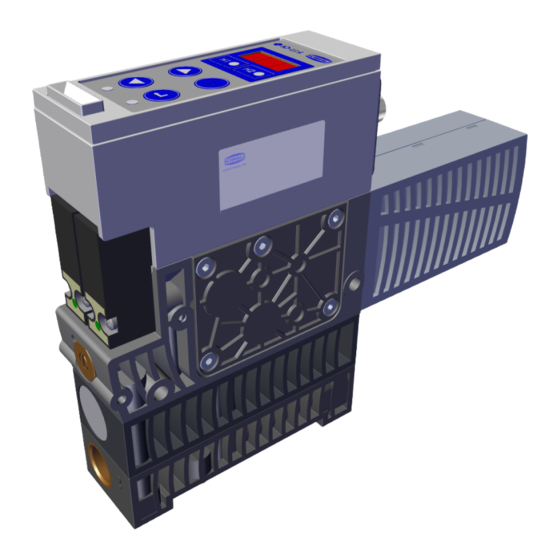
3 Product Description 3.5 Ejector Structure G3/8" vacuum connection in H version (la- Electrical connection, 1xM12-8 or 2xM12-5 bel: 2 [V]) Power blow-off module Silencer Valve screw for blow off flow rate Mounting holes (2x Ø 5.5 mm) Manual actuation of pilot valves G3/8"... - Page 13 3 Product Description LED for "Blow-off" process state H2 limit value LED DOWN BUTTON MENU BUTTON UP BUTTON ENTER BUTTON H1 limit value LED LED for "Suction" process state Display Condition monitoring state indicator IO-Link symbol (product is equipped with —...
- Page 14 3 Product Description Status display for system vacuum During regular suction cycles, the status display is used to display the current system vacuum level in rela- tion to switching points H1 and H2. The status display turns off when a regular suction cycle ends. Status indicator, pos.
-
Page 15: Technical Data
4 Technical Data 4 Technical Data 4.1 Display Parameters Parameter Value Unit Comment Display digit Red 7-segment LED display Resolution ± 2 digit / mbar Unit = mbar Accuracy ± 3 % FS = 25° C, based on FS (full-scale) final value Linearity error ±... -
Page 16: Mechanical Data
4 Technical Data SX(M)Pi – xx – NO/IMP – xx – M12 Power consumption from U — — = 19.2 V = 24.0 V = 26.4 V SX(M)Pi – xx – NC – xx – M12 Power consumption from U — — = 19.2 V = 24.0 V = 26.4 V Voltage of signal output... - Page 17 4 Technical Data Type SXMPi15 SXMPi20 SXMPi25 SXMPi30 Nozzle size [mm] Max. vacuum Suction rate [l/min] Max. blow off capacity [l/min] Air consumption [l/min] Sound level , unobstructed suc- tion [dBA] Sound level , suction [dBA] Weight [kg] 0.91 At 4.5 bar 4.4.2 Factory Settings Code Parameter...
- Page 18 4 Technical Data 4.4.3 Dimensions Variant SXPi ...H G3/8" M12 ex- M5-IG — internal ternal thread thread SXMPi ...H G3/8" M12 ex- M5-IG internal ternal thread thread Variant SXPi ...H 35.5 SXMPi ...H 35.5 All specifications are in mm 18 / 84 EN-US ·...
- Page 19 4 Technical Data Variant SXPi ...Q M12 ex- — ternal thread SXMPi ...Q M12 ex- ternal thread Variant SXPi ...Q SXMPi ...Q All specifications are in mm GP2 base plate, "Quick Change Adapter" G3/8" internal thread All specifications are in mm 4.4.4 Maximum Torque Connection Max.
- Page 20 4 Technical Data 4.4.5 Pneumatic circuit plans SXMPi ...NO... SXMPi ...NC... SXMPi ...IMP... SXMPi ...IMP...PC 20 / 84 EN-US · 30.30.01.00016 · 03 · 01/23...
- Page 21 4 Technical Data SXPi ...NO... SXPi ...NC... SXPi ...IMP... SXPi ...IMP-PC EN-US · 30.30.01.00016 · 03 · 01/23 21 / 84...
-
Page 22: Operating And Menu Concepts
5 Operating and Menu Concepts 5 Operating and Menu Concepts The ejector is operated using four buttons on the foil keypad: MENU BUTTON UP BUTTON ENTER BUTTON DOWN BUTTON Settings are configured in software menus. The following menus are available: • Main menu: For standard applications •... - Page 23 5 Operating and Menu Concepts Starting the system menu: 4 Press simultaneously for about three seconds. ð The display flashes [-5-] ð The system menu opens with the first parameter [cc1]. 5.1.2 Displaying the Operating Mode 4 Press the key from the home screen. ð...
-
Page 24: Main Menu
5 Operating and Menu Concepts 5.2 Main Menu All settings for standard applications can be accessed and configured using the main menu. 5.2.1 Functions in the Main Menu The following table shows an overview of the display codes and parameters in the main menu: Display Parameter Explanation... -
Page 25: Configuration Menu
5 Operating and Menu Concepts 5.3 Configuration Menu The configuration menu is available for applications with special requirements. 5.3.1 Functions in the Configuration Menu The following table shows an overview of the display codes and parameters in the configuration menu: Display Parameter Possible settings Explanation code... -
Page 26: System Menu
5 Operating and Menu Concepts Display Parameter Possible settings Explanation code Value from 001 to PIN code Specify the PIN, lock the menus If the PIN is 000, then the device is not locked. Reset All parameter values are reset to factory settings. The factory settings for the parameters are listed under Factory Settings in the Technical Data section. - Page 27 5 Operating and Menu Concepts Display code Parameter Explanation Serial number The serial number is displayed 5.4.2 Viewing Data in the System Menu 4 Press and hold the buttons simultaneously for at least three seconds. 1. Use the button to select the parameter to be shown. 2.
- Page 28 5 Operating and Menu Concepts 2. Confirm using the button. ð The first three decimal places of the serial number will be displayed (the digits x10 ). The decimal point at the far left lights up. This corresponds to the three-digit block with the highest per- ceived value.
- Page 29 5 Operating and Menu Concepts The counter total is comprised of the three digit blocks together as follows: Displayed section 0. 4 8 61. 8 593. Digit block The current counter total in this example is 48 618 593. Clearing counters There are two different ways of resetting the erasable counters to 0: •...
-
Page 30: Interfaces
6 Interfaces 6 Interfaces 6.1 Basic Principles of IO-Link Communication The ejector is operated in IO-Link mode to enable intelligent communication with a controller. The IO-Link communication takes place using cyclical process data and acyclical ISDU parameters. The ejector’s parameters can be set remotely using IO-Link mode. In addition, the energy and process con- trol (EPC) feature is available. -
Page 31: Description Of Functions
7 Description of Functions 7 Description of Functions 7.1 Operating Modes 7.1.1 Automatic Operation Once the product is connected to the power supply, it is ready for operation and enters automatic mode. This is the normal operating mode, in which the product is operated by the system control unit. A differentiation is made between SIO mode and IO-Link mode. - Page 32 7 Description of Functions 7.1.4 Control Concept for IMP Ejector Variant “Suction” [IN1] “Blow off” [IN2] “Suction” state 0 bar “Blow off” state 0 bar On delivery, the ejector variant IMP is set to “pneumatically OFF.” The ejector only produces suction after a valid pulse has been applied at the “suction” signal input. 7.1.5 Manual Mode NOTE Change the output signals in manual mode...
- Page 33 7 Description of Functions Deactivating Manual Mode ü The ejector is in "manual mode". 4 Press the button. ð The H1 and H2 LEDs cease to flash. The device also exits manual mode when the status of the external signals changes. When the ejector receives an external signal, it switches to automatic mode.
-
Page 34: Monitoring The System Vacuum And Pressure And Defining Limit Values
7 Description of Functions Setting Mode Activated and Deactivated 4 Set the corresponding value using bit 2 in the output process data byte (PDO). A change to bit 0 or bit 1 (suction or blow off) in the PDO also causes the ejector to exit setting mode. This function is only available in IO-Link mode. -
Page 35: Calibrating The Sensors
7 Description of Functions Overview of vacuum and pressure limit values: Limit value parameter Description Vacuum control value Vacuum hysteresis Activation value of “part present” check signal output Hysteresis of “part present” check signal output Part deposited; 20 mbar Pressure activation value Hysteresis pressure 7.3 Calibrating the Sensors Since the sensors installed in the ejector are subject to variation due to the manufacturing process, we... -
Page 36: Blow-Off Modes
7 Description of Functions 7.4.2 Control The ejector switches off vacuum generation when the switching point H1 is reached and switches it back on when the vacuum falls below the hysteresis point (H1-h1). The switch point evaluation for H1 follows the control function. This setting is particularly recommended for airtight workpieces. In this mode, the control function is set to [on]. -
Page 37: Signal Outputs
7 Description of Functions 7.5.3 Externally Time-Controlled Blow-Off The blow-off pulse is triggered externally by the “blow-off” signal. The “blow-off” valve is activated for the time set in the parameter [tbL]. A longer input signal does not increase the blow-off duration. In this mode, the blow-off function is set to [E-t]. -
Page 38: Selecting The Vacuum And Pressure Unit For The Display
7 Description of Functions The duration of the switch-off delay can be set for both signals together under [d1Y] in the configura- tion menu or via IO-Link. Values of 10, 50 or 200 milliseconds can be selected. To deactivate this function, enter the value 0 (= off). -
Page 39: Reset To Factory Settings
7 Description of Functions 7.10 Reset to Factory Settings This function resets the device to its delivered condition. All the switching points and configurations are reset to their factory setting (> See ch. 4.4.2 Factory Set- tings, p. 17)>. Counter readings and sensor zero-point adjustment are not affected by this function. The function is performed using the [rE5] menu item in the configuration menu or via IO-Link. - Page 40 7 Description of Functions To protect the ejector and increase its service life, the ejector automatically deactivates the air saving function and switches to continuous suction if the switching frequency > 6/3 s (more than 6 switching op- erations within 3 seconds). In this case the ejector remains in the Suction state. Additionally: •...
- Page 41 7 Description of Functions Monitor Leakage In control mode, the loss of vacuum/leakage rate (L) within a certain period is monitored (mbar/s). There are two possible statuses. Leakage L < permitted value [-L-] Vacuum P Time t If the leakage is lower than the set value, the vacuum continues to fall until it reaches the switching point H1-h1.
- Page 42 7 Description of Functions • The status indicator flashes green until the next suction cycle When the function is activated, bit 2 is set in the IO-Link parameter 0x0092. In addition, a condition moni- toring event is signaled by bit 6 in the process data input byte. Monitoring is carried out during each con- trol cycle.
- Page 43 7 Description of Functions When the condition monitoring function is activated, the status indicator provides the following informa- tion: Status indicator Behavior Condition monitoring func- Ejector response tion Green Flashing Leakage (greater than -L-) Continuous suction Valve switching frequency Continuous suction (greater than 6/3s) Flashing Control threshold (H1 not...
- Page 44 7 Description of Functions System operation Status indicator Description CM “evacuation time” • Flashing red function • OUT3 Suction cycle with vac- • Control Shutoff uum control, • Flashing green during which the valve protection function is • OUT3 triggered [ctr=on] Key: S: Suction ON...
- Page 45 7 Description of Functions • The DAF status is displayed via the diagnostics display • The display shows [diA] during the evaluation • The evaluation is ended once suction/blow-off recommences System status Leakage Diagnostics display OUT1* OUT3* TIGHT < 67 mbar/s Green MINOR LEAKAGE 67 to 133 mbar/s...
- Page 46 7 Description of Functions Percentage-based air consumption measurement: The ejector calculates the air consumption from the last suction cycle as a percentage. This value corre- sponds to the ratio for the full duration of the suction cycle and the active suction and blow-off times. Absolute air consumption volume: Ejectors with an integrated pressure sensor offer an absolute air consumption measurement in addition to the percentage-based air consumption measurement.
- Page 47 7 Description of Functions Performance calculation The performance calculation helps in evaluating the system status. The performance of the gripping sys- tem can be assessed based on the measurement of the dynamic pressure. Optimal configuration of gripping systems leads to low dynamic pressure and thus to high performance. Conversely, badly configured systems achieve low performance.
-
Page 48: Checking The Delivery
1. Compare the entire delivery with the supplied delivery notes to make sure nothing is missing. 2. Damage caused by defective packaging or occurring in transit must be reported immediately to the carrier and J. Schmalz GmbH. 48 / 84 EN-US · 30.30.01.00016 · 03 · 01/23... -
Page 49: Installation
9 Installation 9 Installation 9.1 Installation Instructions CAUTION Improper installation or maintenance Personal injury or damage to property 4 During installation and maintenance, make sure that the product is disconnected and depressurized and that it cannot be switched on again without authorization. For safe installation, the following instructions must be observed: •... - Page 50 9 Installation The ejector can be mounted in a number of different ways: 1.) Side mounting 4 There are two 5.5 mm through-holes for mounting the ejector. Use screws at least 50 mm in length. Use washers if you are using fastening screws M4 for the mounting process. The ejector must be attached using at least 2 screws;...
- Page 51 9 Installation a) Top attachment b) Side attachment ü Mount the quick change adapter mechanically using two M6 Allen screws (ISO 4762). Compressed air at 1 Vacuum at 2 ü Connect the pneumatic systems: compressed air to the connection marked 1 (G3/8"); vacuum to the connection marked 2 (G3/8").
-
Page 52: Pneumatic Connection
9 Installation 2. Ensuring that the centering pins are aligned correctly, place the ejector on the Quick Change adapter and push it down as far as it will go. 3. Allow the release lever to extend back to its original position. ð... - Page 53 9 Installation CAUTION Noise pollution due to incorrect installation of the pressure and vacuum connec- tions Hearing damage 4 Correct installation. 4 Wear ear protectors. 9.3.1 Connecting the Compressed Air and Vacuum To ensure problem-free operation and a long service life for the product, only use adequately maintained compressed air and take the following requirements into account: •...
- Page 54 9 Installation How to Perform Pneumatic Connection for Ejector Variant H Only screw unions with cylindrical G-threads are permitted to be used for the connections! Compressed air connection Vacuum connection The compressed air connection G3/8" is marked with the number 1 on the ejector. 4 Connect compressed air hose.
-
Page 55: Electrical Connection
9 Installation 4 The pneumatic connection is performed by connecting the ejector plug to the Quick Change adapter. 9.4 Electrical Connection NOTE Change of output signals when product is switched on or plug is connected Personal injury or damage to property 4 Electrical connection may be performed only by specialists who can evaluate the effects of signal changes on the overall system. - Page 56 9 Installation PIN assignment with 2x 5-pin M12 plug Plug Wire Symbol Function color SIO operation IO-Link operation Brown Supply voltage for actu- Supply voltage for actu- ator ator White “Blow off” signal input — Blue Actuator ground Actuator ground Black “Suction”...
- Page 57 IN3 / — “DAF” signal input — When Schmalz connection line part no. 21.04.05.00080 is used When Schmalz connection line part no. 21.04.05.00079 DAF analysis function Observe the following connection instructions: • The maximum cable length is 30 m in SIO operation and 20 m in IO-Link op- eration.
-
Page 58: Operation
10 Operation 10 Operation 10.1 General Preparations WARNING Extraction of hazardous media, liquids or bulk material Personal injury or damage to property! 4 Do not extract harmful media such as dust, oil mists, vapors, aerosols etc. 4 Do not extract aggressive gases or media such as acids, acid fumes, bases, biocides, dis- infectants or detergents. - Page 59 10 Operation Start of operations A typical handling cycle is divided into the following three phases: • Phase 1: Suction, switching steps 1 and 2 • Phase 2: Deposit, switching steps 3 and 4 • Phase 3: Idle state, switching steps 5 and 6 To check whether sufficient vacuum has built up, the limit value H2 is monitored by an integrated vacuum sensor during suction and output to the higher-level controller via OUT.
- Page 60 10 Operation The device supports IO-Link revision 1.1 with fifteen bytes of input data and four bytes of output data. It is also compatible with IO-Link masters that use revision 1.0 and above. In this case, one byte of input data and one byte of output data are supported.
- Page 61 10 Operation Vacuum Time Suction ON Blow off ON Suction ON Blow off OFF Suction OFF Condition monitoring Energy monitoring Predictive maintenance Condition monitoring [CM] Condition monitoring events that occur are immediately signaled by the associated bit in the process data byte during the suction cycle.
-
Page 62: Troubleshooting
11 Troubleshooting 11 Troubleshooting 11.1 Help with Malfunctions Fault Possible cause Solution 4 Check electrical connection and pin No communication Incorrect electrical connection assignment 4 Check the controller configuration Higher-level controller not cor- rectly configured 4 Check for the appropriate IODD IODD connection does not work 4 Check electrical connection and pin Ejector does not re- No actuator supply voltage... -
Page 63: Warnings And Error Messages In Io-Link Mode
11 Troubleshooting Errors In SIO mode, the error messages are shown on the display. Code displayed Explanation Electronics error – internal data management, EEPROM Zero-point adjustment for vacuum/pressure sensor is outside of the tolerance ±3% Actuator supply voltage U too low or not available (display alternates with current vacuum value) Manual operation not possible in “blow off”... - Page 64 11 Troubleshooting Error messages Errors that occur in the device are signaled via bit 7 in the process data byte input (PDI). The parameter 0x0082 can be read out for an exact error analysis. The corresponding error code is transmitted here. Code Description Electronics fault...
-
Page 65: Maintenance
12 Maintenance 12 Maintenance 12.1 Safety Instructions Maintenance work may only be carried out by qualified personnel. 4 Create atmospheric pressure in the ejector’s compressed air circuit before working on the system! WARNING Failure to follow the instructions in these Operating instructions may result in in- juries! 4 Read the Operating instructions carefully and observe the contents. -
Page 66: Cleaning Or Replacing Screens
12 Maintenance 12.4 Cleaning or Replacing Screens The vacuum and compressed air connections contain screw-in or press-in screens. Dust, chippings and other solid materials may be deposited in the screens over time. 4 If there is a noticeable reduction in performance, simply screw off the screens and clean or replace them. -
Page 67: Warranty
13 Warranty 13 Warranty This system is guaranteed in accordance with our general terms of trade and delivery. The same applies to spare parts, provided that these are original parts supplied by us. We are not liable for any damage resulting from the use of non-original spare parts or accessories. The exclusive use of original spare parts is a prerequisite for the proper functioning of the ejector and for the validity of the warranty. -
Page 68: Spare And Wearing Parts, Accessories
14 Spare and Wearing Parts, Accessories 14 Spare and Wearing Parts, Accessories 14.1 Spare and Wearing Parts Maintenance work may only be carried out by qualified personnel. WARNING Risk of injury due to incorrect maintenance or troubleshooting 4 Check the proper functioning of the product, especially the safety features, after every maintenance or troubleshooting operation. -
Page 69: Decommissioning And Recycling
15 Decommissioning and Recycling 15 Decommissioning and Recycling 15.1 Disposing of the Product 1. Dispose of the product properly after replacement or decommissioning. 2. Observe the country-specific guidelines and legal obligations for waste prevention and disposal. 15.2 Materials Used Component Material Housing PA6-GF Inner components Aluminum alloy, anodized aluminum alloy, brass, galvanized steel, stainless-steel, PU, POM... -
Page 70: Overview Of Display Codes
16 Overview of Display Codes 16 Overview of Display Codes Display Parameter Comment code Limit value H1 Switch-off value for air-saving function/control Hysteresis value h1 Hysteresis of control Limit value H2 Activation value of “part present” check signal output Hysteresis value h2 Hysteresis of “part present”... - Page 71 16 Overview of Display Codes Display Parameter Comment code Normally closed con- Signal output setting as normally closed contact tact (normally closed) Control Set the air saving function (control function) Air saving function on The air saving function is activated Control function on Switches on the air saving function with leakage monitoring with leakage monitor-...
-
Page 72: Declarations Of Conformity
17 Declarations of Conformity 17 Declarations of Conformity 17.1 EC Declaration of Conformity EC Declaration of Conformity The manufacturer Schmalz confirms that the product Ejector described in these operating instructions ful- fills the following applicable EC directives: 2014/30/EU Electromagnetic Compatibility 2011/65/EU RoHS Directive The following harmonized standards were applied: EN ISO 12100... - Page 73 IO-Link Schnittstelle SXPi series 21.10.01.00061/00 15.01.2013 J. Schmalz GmbH Johannes-Schmalz-Str. 1, D 72293 Glatten Tel.: +49(0)7443/2403-0 Fax: +49(0)7443/2403-259 info@schmalz.de IO-Link SIO-Mode Frame-Typ Baudrate 38,4 kBd Minimum cycle time 3,0 ms Processdata input 1 byte Processdata output 1 byte ...
- Page 74 Data Parameter Value range Access Default value Remark width Identification 0x07 0x00 Vendor ID 2 bytes 0x00EA = 234 = J. Schmalz GmbH 0x08 0xEA 0x09 0x01 Device ID 3 bytes Internal code number 0x0A 0x87 0x0B 0x72 0x0010...
- Page 75 0 - 1 1 = Restore; After restoring 0 Diagnose Error 1-99 = Error-code 0x0082 Exx Error-Code 1 byte 0-255 100 - 199 = Internal error code J. Schmalz GmbH 3 von 5 SXPi_SXMPi_V2 Data Dictionary 21.10.01.00061_01 2014-07-29.xls...
- Page 76 Time from H2 to H1 [ms] Energy Monitoring [EM] 0x009B Air consumption per cycle in percent 1 byte 0 - 100 Air consumption of last sucking cycle [%] J. Schmalz GmbH 4 von 5 SXPi_SXMPi_V2 Data Dictionary 21.10.01.00061_01 2014-07-29.xls...
- Page 77 Vacuum mbar H1-h1 H2-h2 time Vacuum On Vacuum On Blow-off On Blow-off Off Vacuum Off Condition Monitoring Energy Monitoring Predictive Maintenance J. Schmalz GmbH 5 von 5 SXPi_SXMPi_V2 Data Dictionary 21.10.01.00061_01 2014-07-29.xls...
- Page 78 IO-Link Schnittstelle SXPi series 21.10.01.00062/00 15.01.2013 J. Schmalz GmbH Johannes-Schmalz-Str. 1, D 72293 Glatten Tel.: +49(0)7443/2403-0 info@schmalz.de IO-Link SIO-Mode Frame-Typ Baudrate 38,4 kBd Minimum cycle time 3,0 ms Processdata input 1 byte Processdata output 1 byte Process Data...
- Page 79 Data Parameter Value range Access Default value Remark width Identification 0x07 0x00 Vendor ID 2 bytes 0x00EA = 234 = J. Schmalz GmbH 0x08 0xEA 0x09 0x01 Device ID 3 bytes Internal code number 0x0A 0x87 0x0B 0x73 0x0010...
- Page 80 Reset erasable counters 1 byte 0 - 1 1 = Reset erasable counters 0 = Nothing 0x007B rES Factory defaults 1 byte 0 - 1 1 = Restore; After restoring 0 J. Schmalz GmbH 3 von 5 SXPi_SXMPi_V2 Data Dictionary 21.10.01.00061_01 2014-07-29.xls...
- Page 81 Dynamic pressure of last sucking cycle [mbar] 0x00A2 Quality 1 bytes 0 - 100 Quality of last sucking cycle [%] 0x00A3 Performance 1 bytes 0 -100 Performance of last sucking cycle [%] J. Schmalz GmbH 4 von 5 SXPi_SXMPi_V2 Data Dictionary 21.10.01.00061_01 2014-07-29.xls...
- Page 82 Vacuum mbar H1-h1 H2-h2 time Vacuum On Blow-off On Blow-off Off Vacuum On Vacuum Off Condition Monitoring Energy Monitoring Predictive Maintenance J. Schmalz GmbH 5 von 5 SXPi_SXMPi_V2 Data Dictionary 21.10.01.00061_01 2014-07-29.xls...
- Page 83 EN-US · 30.30.01.00016 · 03 · 01/23 83 / 84...
- Page 84 At Your Service Worldwide Vacuum automation Handling systems WWW.SCHMALZ.COM/AUTOMATION WWW.SCHMALZ.COM/EN-US/VACUUM-LIFTERS- AND-CRANE-SYSTEMS J. Schmalz GmbH Johannes-Schmalz-Str. 1 72293 Glatten, Germany T: +49 (0) 7443 2403-0 schmalz@schmalz.de WWW.SCHMALZ.COM...
Need help?
Do you have a question about the X-Pump - SXPi and is the answer not in the manual?
Questions and answers