Table of Contents
Advertisement
Operator's IVlanuai
CRRF r. MgN°
42"- 2 STAGE SNOW THROWER
TRACTOR ATTACHMENT
IVlodei No. 486.24837
DO NOT RETURN
TO STORE
For Missing Parts or Assembly
Questions
Call 1-866-576-8388
FOR TRACTORS
WiTH MODEL NUMBERS
BEGiNNiNG
WiTH 917.
CAUTION:
Before using this product, read
this manual and follow all Safety
Rules and Operating
Instructions.
,, Safety
,, Assembly
,, Operation
,, Maintenance
,, Parts
Sears, Roebuck
and Co., Hoffman
Estates, IL 60179 U.S.A.
www.sears.com/craftsman
PRINTED IN U.S.A.
FORM NO. 41361 rev. (07/30/10)
Advertisement
Table of Contents

Related Manuals for Craftsman 486.24837


Summary of Contents for Craftsman 486.24837
- Page 1 Operator's IVlanuai CRRF r. MgN° 42"- 2 STAGE SNOW THROWER TRACTOR ATTACHMENT IVlodei No. 486.24837 FOR TRACTORS CAUTION: Before using this product, read this manual and follow all Safety Rules and Operating Instructions. Sears, Roebuck and Co., Hoffman www.sears.com/craftsman PRINTED IN U.S.A.
-
Page 2: One Year Full Warranty
Sears, Roebuck and Co., D817WA, Hoffman Estates, IL 60179 These and other accessories are recommended for use with your unit. Call 1-800-4-MY-HOME® to find out if they are available. If available, they may be purchased at most Craftsman outlets or by calling 1-800-4-MY-HOME®. WHEEL WEIGHT The model number and serial numbers will be found on a decal attached to the snow thrower. - Page 3 Anypower e quipment cancause injury ifoperated i mproperly oriftheuserdoesnotunderstand how tooperate t heequipment. Exercise caution atalltimes, w henusing power equipment. • Read thisowner's manual carefully andknowhowto operate yoursnowthrower a ndhowto stoptheunit anddisengage t hecontrols quickly. Never a llowchildren tooperate theequipment. Never a llowadults to operate theequipment without proper instruction.
- Page 4 43351 43020 49933 48106 46938 47630 49948 47631 43086 R19172410 712-3083 43019 HA21362 SHOWN ACTUAL SIZE 43840 43084 43350 710-0890A R19171616 43088 _\\\\\\ 44695 43082 47810 r--qq 43182 43063 43661 • JL 43682 44215 _ ... 43081 47605, 43070 24817 43003 46584 47598...
-
Page 5: Parts List
46959 43055 46963 IMPORTANT: Not all items supplied in the hardware bag will be needed for your particular tractor. Unneeded items may be discarded after you have completed assembly and checked operation of unit. DO NOT DISCARD the two spare shear bolts (K) and 5/16"... -
Page 6: Package Contents
Housing Assembly LiftHandle andCable ChuteCrankRodAssembly Support T ube, C rankRod Engagement Rod(Notusedonsomemodels) CableBracket Engine Pulley Keeper ( Notusedonsomemodels) ChuteandControl C ableAssembly ClutchIdlerAssembly 10. RearPulley Frame Bracket (2) 11. Anti-rotation B racket. ONLY ITEMS NEEDED 12. FrontPulley Frame Bracket (2) 13. V-Belt, D rive56"(#48138) 14. - Page 7 LOCATE TRACTOR'S MODEL Look under your tractor seat to locate the model number label shown below. This manual if for tractors with model numbers that start with 917 as shown below. 917 MODEL TRACTORS CRRFTXllIRH + CONFORMS ANSi B71,1=2003 SAFETY III |1 111111|1| IIIIIIIl lllllllllll 000000A000000...
-
Page 8: Install Side Plates
IDENTIFYYOUR TRACTOR STEP 1: (SEE FIGURE 1) Look under the front of your tractor. If there is a single mower deck suspension bracket located underneath the middle of the front axle, continue on to step 2. if your tractor does not have a mower deck suspension bracket underneath front axle, skip to step 21 on page 14 for tractors... -
Page 9: Install Hanger Brackets And Shoulder Bolts
iNSTALL HANGER BRACKETS BOLTSTO OUTSIDE OF FRAME STEP 5: (SEE FIGURE 5) Remove the bolt, if present, in the hole directly behind the brake rod on the left side of the tractor frame. Attach the L.H. Hanger Bracket (tube facing out) to the hole using a 5/16"... - Page 10 THIS SECTION IS FOR TRACTORS MAN UAL ATTACHM ENT CLUTCH if your tractor has an electric attachment clutch go to step 14 on page 12. STEP 7: (SEE FIGURE 7) Attach the cable bracket to the double hole in the clutch/idler assembly as shown, using a 5/16"...
-
Page 11: Attach Clutch Idler Assembly To Tractor
STEP11: (SEEFIGURE 11) Find the cable clip that is attached to the left side of the tractor frame underneath the footrest. Open the clip and remove the mower clutch cable. Do not remove the clip from the tractor frame. The cable reattaches to the clip when using the mower deck. - Page 12 THIS SECTION IS FOR TRACTORS ELECTRIC ATTACHMENT CLUTCH STEP 14: (SEE FIGURE 14) • Turn the clutch idler assembly upside down. • Hook the spring onto the end of the bolt that extends through the nut on the bottom of the upper idler arm.
- Page 13 STEP 18: (SEE FIGURE 17) Turn the clutch/idler assembly right side up. Slightly loosen the hex bolt next to the flat idler pulley. Install the drive belt down between the hex bolt and the flat idler pulley with the flat side of the belt against the pulley.
-
Page 14: Dual Front Deck Suspension Brackets
iNSTRUCTiONS FOR TRACTORS FRONT DECK SUSPENSION FASTEN SIDE PLATES TO TRACTOR if your tractor resembles figure 20, go to step 21. If your tractor resembles figure 22, go to step 23. STEP 21: (SEE FIGURE 20) Remove bolts from front three holes shown. If a bolt is present in the fourth hole, replace it with a 5/16"... - Page 15 iNSTALLiNG HANGER BRACKETS For better clearance, lower the tractor's suspension arms using the attachment lift lever. STEP 26: (SEE FIGURE 25 or 26) On Tractors With Foot Rest Brackets Remove the bolt and nut that fasten the L.H. and R.H. foot rest brackets to the frame.
- Page 16 iNSTALLiNG CLUTCH/IDLER This section covers the installation of the Clutch/Idler assembly to tractors with attachment clutches that are either rod operated (p. 16), cable operated (p. 18) or electric (p. 20). Use the appropriate instructions for your tractor. ROD OPERATED MANUAL ATTACHMENT CLUTCH STEP 29: (SEE FIGURE 29) •...
- Page 17 STEP32: (SEEFIGURE 32) • Besuretoliftupthefrontendoftheengagement rod asshown whenperforming t henextoperation. You cantemporarily support t herodusing a rubber b and tiedtotheengine pulleykeeper. Attach theclutch/idler assembly t othetractor f rame asfollows. Hooktheassembly's n otched rearpulley frame brackets o ntothetwoshoulder b oltsyou assembled to theinside ofthetractor f rame. L iftthe frontoftheassembly a ndattach ittothe R.H.
- Page 18 CABLEOPERATED M ANUAL ATTACHMENT CLUTCH STEP 35: (SEE FIGURE 35) Assemble the cable bracket to the inner half of the double holes in the bottom of the clutch/idler assembly using two 5/16" × 3/4" carriage bolts and 5/16" nylock nuts. Use the front holes in the cable bracket if your tractor has a 42"...
- Page 19 STEP38: (SEEFIGURE 38) • Move theattachment clutchlever o nthedashpanel t o thedisengaged (down) p osition. Place theclutch/idler assembly o nthefloorontheright sideofthetractor. Attach thetractor's c lutch cable tothecable bracket. Secure thecablehousing guide(groove down) t othe cable bracket u sing theoriginal c ollaranda 5/64"hair cotterpin.
-
Page 20: Electric Attachment Clutches
ELECTRIC ATTACHMENT CLUTCHES STEP41: (SEEFIGURE 41) • Turn theclutchidlerassembly u pside down. Hookthespring(ontotheendoftheboltthatextends through thenutonthebottom oftheupper idler arm.Install a 3/8"hexlocknutontothebolt,leaving enough space forthespring to pivot. SPRING 3/8" HEX LOCK NUT © ATTACH SPRING HERE FIGURE 41 STEP 42: (SEE FIGURE 42) Insert tensioning chains through the holes shown and attach to the springs on the upper and lower idler arms. - Page 21 STEP 45: (SEE FIGURE 44) Turn the clutch/idler assembly right side up. Slightly loosen the hex bolt next to the flat idler pulley. Install the drive belt down between the hex bolt and the flat idler pulley with the flat side of the belt against the pulley.
- Page 22 ASSEMBLY OF THE SNOW THROWER STEP 48: (SEE FIGURE 47) • Place the lift handle into the lift bracket on the right side of the snow thrower. Fasten the handle to the bracket using two 5/16" x 1-3/4" hex bolts and 5/16" Nylock nuts.
- Page 23 STEP52: (SEEFIGURE 51) • Attach thechutecrankrodassembly b rackets t o theplasticbracket o nthe leftsideofthedischarge housing. Alignthechutecrankbracket b eneath the rodsupport b racket a ndassemble b othtotheplastic bracket u sing two5/16" x 1"carriage bolts,5/16" washers and5/16"Nylock nuts. D o nottightenyet. CHUTE CRANK 5/16"...
-
Page 24: Attaching Snow Thrower To Tractor
ATTACHING SNOW THROWER NOTE: An additional person's help may be required to mount the snow thrower to the front of the tractor. STEP 55: (SEE FIGURE 54) • Place the tractor and snow thrower on a flat, level surface so that the tractor can be rolled forward to attach the snow thrower. -
Page 25: Accessories
THE ATTACHMENT STEP 58: (REFER BACKTO FIGURE 54 ON PAGE 24) Lift the front of the snow blower to align the holes in the mounting plates and the side plates. From the left side of the tractor insert the attachment pin through the holes. -
Page 26: Safety Rules
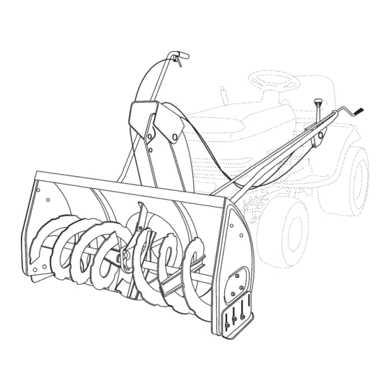
KNOW YOU R SNOW TH ROWER Read this owner's manual and safety rules before operating your snow thrower. Compare the illustration below with your snow thrower to familiarize yourself with the various controls and their locations. LIFT HANDLE UPPER CHUTE LOWER CHUTE SCRAPER PLATE SPIRAL AUGERS, R.H.&... -
Page 27: Raising Andlowering
RAISING ANDLOWERING • Toraise, p ushdownonthelifthandle untilthesnow thrower l ocksintheraised transport p osition. Tolower, p ushdown slightly onthelifthandle andpull thetrigger. W iththetriggerpulled, s lowly lower the snowthrower u ntilit reaches theground. CAUTION: Donotoperate thesnow thrower w ithout r earwheel w eights attached t othetractor t oprovide extra traction andstability. - Page 28 CAUTION: Before servicing oradjusting thesnow thrower, shut o fftheengine, r emove thespark plug wire(s), settheparking b rake andremove t hekey from thetractor i gnition. REPLACING AUGER BELT • Disengage the tractor's attachment clutch. Lower the snow thrower to the ground. Remove the attachment pin.
-
Page 29: Storage
STORAGE RECOMMENDATIONS • Lower the snow thrower to the ground. Remove the snow thrower from the tractor. Clean the snow thrower thoroughly. Wash off any salt deposit which may have dried on the thrower and housing. Any bare metal that has become exposed should be painted or coated with a light oil to prevent rust. - Page 30 REPAIR PARTS FOR MODEL 486.24837 (For Tractors With Model Numbers Beginning 67" 65 21 40, 59 42" SNOW THROWER 4 tz, 537O 40, 59 _¢_ 54 _ With 917) 18 41...
- Page 31 REPAIR PARTS FOR MODEL 486.24837 (For Tractors With Model Numbers Beginning PART NO 05931 Housing, Bearing 65701 Housing Assembly 71464 Gear Assembly 63579 Chute Crank Rod Assembly 63768 Impeller Assembly 24773 Scraper Plate 25982 Shaft, Auger Gearbox 703-2735A Bracket, Chute Crank...
- Page 32 REPAIR PARTS FOR MODEL 486.24837 (For Tractors With Model Numbers Beginning 65 58 60 !6 !6 42" SNOW THROWER With 917) 59--_ C 35._.
- Page 33 REPAIR PARTS FOR MODEL 486.24837 (For Tractors With Model Numbers Beginning With 917) PART NO 64637 Lift Shaft Assembly 710-0865 Hex Bolt, 1/2-13 x 1" 710-0367 Hex Bolt, 5/8-11 x 1-1/2" 711-0332 Pin, Bracket Lift 712-0261 Nut, Hex Lock 5/8-11 Thread...
- Page 34 REPAIR PARTS FOR MODEL 486.24837 (For Tractors With Model Numbers Beginning 40 37 PART NO DESCRiPTiON 43080 Carriage Bolt, 5/16-18 x 3/4" 43064 Hex Lock Nut, 5/16-18 43083 Hex Nut, 5/16-18 43086 Lock Washer, 5/16" 43081 Washer, 5/16" Std. Wrt.
- Page 35 SUGGESTED GUIDE FOR SIGHTING SLOPES FOR SAFE OPERATION OF TRACTOR WITH ATTACHMENT _FOLD ALONG 10 DEGREES WARNING: To avoid serious injury, operate your tractor up and down the face of slopes, never across the face. Do not operate & on slopes greater than 10 degrees. Make turns gradually to prevent tipping or loss of control.
-
Page 36: Troubleshooting
For expert troubleshooting For repair - in your home - of all major brand appliances, lawn and garden equipment, no matter who made it, no matter who sold it! For the replacement owner's manuals that you need to do-it-yourself. For Sears professional and items like garage door openers and water heaters.
Need help?
Do you have a question about the 486.24837 and is the answer not in the manual?
Questions and answers
how do you get the pulley off snow blower 248374 and the number is 66 part number is47026
The document does not provide specific instructions for removing the pulley from the Craftsman snow blower model 486.24837. However, it does mention pulley-related components such as the V-type pulleys (part numbers 46981 and 46982) and associated hardware like hex nuts and spacers. Typically, pulley removal involves loosening and removing the securing hardware, such as hex nuts and lock washers, then carefully sliding the pulley off the shaft. If further details are needed, refer to the full manual or a repair guide.
This answer is automatically generated