Sign In
Upload
Manuals
Brands
Woodward Manuals
Control Systems
AtlasSC 8273-040
Woodward AtlasSC 8273-040 Manuals
Manuals and User Guides for Woodward AtlasSC 8273-040. We have
1
Woodward AtlasSC 8273-040 manual available for free PDF download: Installation And Operation Manual
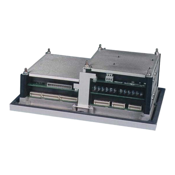
Woodward AtlasSC 8273-040 Installation And Operation Manual (141 pages)
Digital Control
Brand:
Woodward
| Category:
Control Systems
| Size: 2 MB
Table of Contents
Table of Contents
3
Warnings and Notices
8
Electrostatic Discharge Awareness
9
Regulatory Compliance
10
Chapter 1. General Information
12
Introduction
12
Atlassc Control Description
12
Control Versions
12
Control Accessories
13
Figure 1-1. Atlassc Module Layout
13
Figure 1-2. Atlassc Control Layout
14
Figure 1-3. Atlassc Control (8273-040)
15
Figure 1-4. Atlassc Control (8273-041)
16
Figure 1-5. Atlassc Control (8273-042)
17
Figure 1-6. Atlassc Control (8273-043)
18
Chapter 2 Installation
19
Introduction
19
General Installation
19
Shipping Carton
19
Mounting
19
Figure 2-1. Spring Clamp
20
Figure 2-2. Wiring Fixed Terminal
21
Figure 2-3. Fixed Terminals
21
Figure 2-4. Input Power Wiring Diagram
24
Chapter 3. Power Supply Board
25
General Description
25
Figure 3-1. Power Supply Board (601-1008)
25
Specifications
26
Troubleshooting Guide
26
Figure 3-2. Discrete Output Wiring Example
27
Chapter 4. Smartcore Board with Actuators
28
General Description
28
Specifications
28
Figure 4-1. Smartcore Board with Actuators Connections
29
Figure 4-2. Minimum MPU Voltage Graph
30
Smartcore Board Operation
33
Figure 4-3. MPU Interface to the Smartcore Board
33
Figure 4-4. Proximity Probe to the Smartcore Board
34
Figure 4-5A. 4-20 Ma Input Interface to the Smartcore Board
35
Figure 4-5B. 4-20 Ma Input Interface Using External Loop Power
35
Figure 4-6. 0-5 V Input Interface to the Smartcore Board
36
Figure 4-7. Analog Output Interface to the Smartcore Board
36
Figure 4-8. Actuator Output Interface to the Smartcore Board
37
Figure 4-9. Discrete Input Interface to the Smartcore Board
38
Serial I/O Ports
40
Figure 4-10. RS-232 Interface to the Smartcore Board
41
Figure 4-11. RS-422 Interface to the Smartcore Board
41
Figure 4-12. RS-485 Interface to the Smartcore Board
41
Configurable Port (Com 1)
42
Figure 4-13. Alternate Multipoint Wiring
42
Figure 4-14. RS-422 Wiring Diagram (Com 1)
43
Figure 4-15. RS-485 Wiring Diagram (Com 1)
44
Figure 4-16. RS-232 Wiring Diagram (Com 1)
44
Figure 4-17. RS-422 Wiring Diagram (Com 2)
45
Configuration Port (Com 3)
46
Figure 4-18. RS-485 Wiring Diagram (Com 2)
46
Figure 4-19. RS-232 Wiring Diagram (Com 2)
46
Figure 4-20. RS-232 Wiring Diagram (Com 3)
47
Chapter 5. Analog Combo Board
50
General Description
50
Figure 5-1. Analog Combo Board Connections
50
Figure 5-2. Minimum MPU Voltage
54
Figure 5-3. MPU Interface to the Analog Combo Board
55
Figure 5-4A. 4-20 Ma or Thermocouple Input Interface to the Analog Combo Board
56
Figure 5-4B. 4-20 Ma Input Interface Using External Loop Power
56
Figure 5-5. 4-20 Ma Input Interface to the Analog Combo Board
57
Figure 5-6. RTD Input Interface to the Analog Combo Board
57
Figure 5-7. Analog Output Interface to the Analog Combo Board
58
Troubleshooting Guide
60
Figure 6-1. Terminal Block Covers
63
Figure 6-2. Powersense Board Connections
64
Figure 6-3. Wye Connected System
69
Figure 6-4. Wye Connected System
70
Figure 6-5. Wye Connected System
71
Figure 6-6. Delta Connected System
72
Figure 6-7. Delta Connected System
73
Figure 6-8. CT Interface to the Powersense Board
76
Figure 6-9. CT Interface to the Powersense Board
77
Figure 6-10. Speed Bias Output Interface to the Powersense Board
78
Figure 6-11. Speed Bias Output Interface to the Powersense Board
78
Figure 6-12. Voltage Bias Output Interface to the Powersense Board
79
Figure 6-13. Voltage Bias Output Interface to the Powersense Board
79
Figure 6-14. LON Interface to the Powersense Board
80
Troubleshooting Guide
81
Chapter 7. 12-Channel Relay Module
83
General Information
83
Relay Information
83
Figure 7-1. 12-Channel Relay Module
83
Shielding
84
Board Status Lights
84
Wiring
84
Figure 7-2. 12-Channel Relay Module Connections
85
Chapter 8. Distributed I/O
86
General Description
86
Serial (Modbus) Interface
86
Figure 8-1. Automation Direct Terminator I/O Configuration
92
Figure 8-2. MODBUS_M Block Example
92
Figure 8-3. T1K-MODBUS Adapter Addressing Table
95
Figure 8-4. MODBUS_M Block RPT Example
96
Figure 8-5. MODBUS_M Block Boolean Write RPT Example
96
Figure 8-6. MODBUS_M Block Boolean Read RPT Example
97
Figure 8-7. MODBUS_M Block Analog Read RPT Example
97
Automation Direct Modbus Interface (T1K-MODBUS) Module
98
Figure 8-8. MODBUS_M Block Analog Write RPT Example
98
Figure 8-9. T1K-MODBUS Dip Switch Settings
99
Figure 8-10. Automation Direct Modbus RS-232 Serial Connection
99
Automation Direct Discrete Input (Sink) (T1K-08ND3) Module
100
Figure 8-11. T1K-08ND3 Sink/External Power Configuration
100
Figure 8-12. T1K-08ND3 Module Wiring
101
Figure 8-13. T1K-08ND3 Memory Map
101
Figure 8-14. T1K-08ND3 Read GAP Blocks
101
Automation Direct Discrete Input (Sink) (T1K-16ND3) Module
102
Figure 8-15. T1K-16ND3 Sink/External Power Configuration
102
Figure 8-16 T1K-16ND3 Module Wiring
103
Figure 8-17. T1K-16ND3 Memory Map
103
Automation Direct Discrete Output (Sink) (T1K-16TD1) Module
104
Figure 8-18. T1K-16ND3 Read GAP Blocks
104
Figure 8-19. T1K-16ND3 Module to Relay Module Wiring
105
Figure 8-20. T1K-16TD1 Module Memory Map
105
Automation Direct Relay Output (T1K-08TRS) Module
106
Figure 8-21. T1K-16TD1 GAP Write Blocks
106
Figure 8-22. T1K-08TRS Module Wiring
107
Figure 8-23. T1K-08TRS Module Memory Map
107
Figure 8-24. T1K-08TRS GAP Write Blocks
107
Automation Direct Analog Input (T1F-16AD-1) Module
108
Figure 8-25. T1F-16AD-1 Module Wiring
108
Figure 8-26. T1F-16AD-1 Analog Input Module Memory Map
109
Figure 8-27. T1F-16AD-1 Current Input Module Resolution
109
Automation Direct Analog Output (T1F-16DA-1) Module
110
Figure 8-28. T1F-16AD-1 GAP CURVE_2D Scaling Blocks
110
Figure 8-29. T1F-16DA-1 Module Wiring
111
Figure 8-30. T1F-16DA-1 Module Memory Map
112
Figure 8-31. T1F-16DA-1 Control Byte Table
113
Figure 8-32. T1F-16DA-1 Control Byte GAP Block
113
Figure 8-33. T1F-16DA-1 Current Output Module Resolution
114
Figure 8-34. T1F-16DA-1 GAP Analog Write Blocks
114
Automation Direct Thermocouple Input (T1F-14THM) Module
115
Figure 8-35. T1F-14THM Module Wiring
116
Figure 8-36. T1F-14THM Thermocouple Module Memory Map
117
Figure 8-37. for T1F-14THM Jumper Configuration Tables
117
Figure 8-38. T1F-14THM Jumper Locations
118
Figure 8-39. T1F-14THM GAP DIVIDE Blocks
118
Chapter 9. Communications
119
Figure 9-1. ASCII/RTU Representation of 3
119
Chapter 10. Programming and Service Tools
122
Introduction
122
Connecting the Atlassc Control to a PC
122
Figure 10-1. Connecting the Atlassc Control to a PC
122
Loading Watch Window and Servlink on the PC
123
Applying Power to the Atlassc Control
123
Opening Communications with the Atlassc Control
123
Chapter 11. Product Support and Service Options
129
Product Support Options
129
Product Service Options
129
Returning Equipment for Repair
130
Replacement Parts
131
Engineering Services
131
Contacting Woodward's Support Organization
131
Technical Assistance
132
Ppendix a
133
Acronyms and Glossary of Terms
133
Acronyms
133
Glossary of Terms
134
Ppendix B
135
Wiring Diagrams
135
Figure B-1. Smartcore Board with Actuators Connections
135
Figure B-2. Analog Combo Board Connections
136
Figure B-3. Power Supply Board Connections
136
Figure B-4. Powersense Board Connections
137
Figure B-5. 12-Channel Relay Module Connections
138
Appendix C. Flash Codes
139
Revision History
140
Advertisement
Advertisement
Related Products
Woodward AtlasSC 8273-041
Woodward AtlasSC 8273-042
Woodward AtlasSC 8273-043
Woodward Atlas-II 8273-553
Woodward Atlas-II 8273-557
Woodward Atlas-II 8273-562
Woodward Atlas-II 8273-570
Woodward Atlas-II 8273-584
Woodward 8273-1018
Woodward 8273-587
Woodward Categories
Controller
Control Unit
Relays
Control Systems
Industrial Equipment
More Woodward Manuals
Login
Sign In
OR
Sign in with Facebook
Sign in with Google
Upload manual
Upload from disk
Upload from URL