Table of Contents
Advertisement
Available languages
Available languages
Quick Links
ATTACH YOUR RECEIPT HERE AND REGISTER YOUR FAN AT FANIMATION.COM
READ AND SAVE THESE INSTRUCTIONS
Date Code
For best and quickest service please provide date code. You can find the date code on the carton,
hand-held remote (inside of the battery compartment), receiver or top of fan housing.
Questions, problems, missing parts? Before returning to your retailer, call our customer
service department at 1-888-567-2055, 8 a.m.-5 p.m., EST, Monday-Friday.
Purchase Date
™
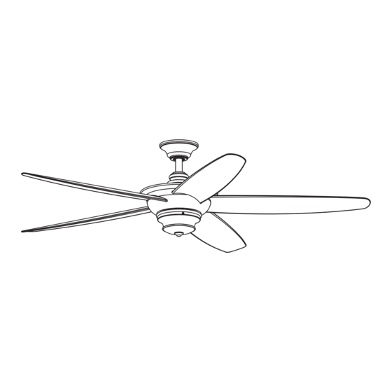
FLORID CEILING FAN
Net Weight
MODEL #
LP8300**
Español p. 21
24.98 lbs (11.33 kgs)
Advertisement
Chapters
Table of Contents

Related Manuals for Fanimation FLORID LP8300 Series


Summary of Contents for Fanimation FLORID LP8300 Series
- Page 1 ™ FLORID CEILING FAN MODEL # LP8300** Español p. 21 ATTACH YOUR RECEIPT HERE AND REGISTER YOUR FAN AT FANIMATION.COM READ AND SAVE THESE INSTRUCTIONS Date Code Purchase Date Net Weight 24.98 lbs (11.33 kgs) For best and quickest service please provide date code. You can find the date code on the carton, hand-held remote (inside of the battery compartment), receiver or top of fan housing.
- Page 2 Important Safety Instructions WARNING: To avoid fire, shock and serious personal injury, follow these instructions. 1. Read your owner’s manual and safety information before installing your new fan. Review the accompanying assembly diagrams. 2. Before servicing or cleaning unit, switch power off at service panel and lock service panel disconnecting means to prevent power from being switched on accidentally.
-
Page 3: Table Of Contents
Fanimation. 7. Fanimation reserves the right to modify or discontinue any product at any time and may substitute any part under this warranty. 8. Under no circumstances may a fan be returned without prior authorization from Fanimation. The receipt of purchase must accompany authorized returns and must be sent freight prepaid to Fanimation. -
Page 4: Unpacking Instructions
Fanimation. Substitution of parts or accessories not designated for use with this product by Fanimation could result in personal injury or property damage. Contact your retail store for missing or damaged parts. -
Page 5: Energy Efficient Use Of Ceiling Fans
8 - 9 feet from floor to the blade for optimal ceiling fan at low speed in the clockwise direction. airflow. Consult your Fanimation Retailer for optional This produces a gentle updraft, which forces warm air mounting accessories. - Page 6 Electrical and Structural Requirements (Continued) Deep box with brace (Figure 3) Paired with a deep box, this hanger is meant to span CEILING JOIST between two joists and takes the place of wooden blocking. WARNING To reduce the risk of fire, electric shock, or personal injury, mount to outlet box marked acceptable for fan support of 15.9 kg (35 lbs) or less and use mounting screws provided with the outlet box.
-
Page 7: How To Assemble Your Ceiling Fan Blades
How to Assemble Your Ceiling Fan Blades Remove the three stabilizer tabs and plastic bag from the motor. Discard the stabilizer tabs. (Figure 1) Stabilizer Motor Tabs Assembly Figure 1 Remove the two set screws and locking nuts of the Downrod Support downrod support from the motor assembly then retain the screws and nuts for How to Assemble Your... - Page 8 How to Assemble Your Ceiling Fan Blades (Continued) 5. Slide the blade through the slot in the motor assembly and attach to the motor hub using the 3/16˝-24 serrated head screws and flat washers. 3/16”-24 Tighten serrated head screws with flat washers to Serrated Head Screws secure the blade to the hub of motor assembly.
-
Page 9: How To Assemble Your Ceiling Fan
How to Assemble Your Ceiling Fan Remove the hanger ball portion from the downrod/ hanger ball assembly by loosening the set screw in the hanger ball until the ball falls freely down the downrod. Remove the pin from the downrod, then Downrod remove the hanger ball. - Page 10 How to Assemble Your Ceiling Fan (Continued) 6. Reinstall the hanger ball on the downrod as follows. Route the black and white wires through the hanger ball. Position the pin through the two holes in the downrod and align the hanger ball so the pin is captured in the groove in the top of the hanger ball.
-
Page 11: How To Hang Your Ceiling Fan
How to Hang Your Ceiling Fan WARNING To avoid possible fire or shock, be sure electricity is turned off at the main fuse box before hanging. Main Fuse Box (Figure 1) NOTE: If you are not sure if the outlet box is grounded, contact a licensed electrician for advice, as it must be Figure 1 grounded for safe operation. -
Page 12: How To Wire Your Ceiling Fan
How to Wire Your Ceiling Fan NOTE: The remote unit has 32 different code Remote Control combinations. To prevent possible interference from Receiver or to other remote units, simply change the combination code in the remote and receiver. To set the code on receiver unit, slide dip switches to the same positions as set on the remote. -
Page 13: How To Install Your Canopy Housing
How to Install Your Canopy Housing NOTE: This step is applicable after the neccessary wiring is completed. Assemble canopy by rotating key slot in canopy over shoulder screw in hanger bracket, taking care not Ceiling to pinch the wires. Tighten shoulder screw. Fully Canopy assemble and tighten second shoulder screw that was previously removed. - Page 14 How to Assemble Your Adapter-Switch Cup (Continued) Assemble the switch cup adapter to the support bracket using the two key slots in the switch cup adapter. Replace the previously removed screw and securely tighten all three screws. (Figure 3) Motor Assembly Switch Cup Adapter...
-
Page 15: How To Operate Your Ceiling Fan
How to Operate Your Ceiling Fan IMPORTANT: Using a full range dimmer switch (not included) to control fan speed will damage the fan. To reduce the risk of fire or electrical shock, do not use a full range dimmer switch to control the fan speed. (Figure 1) For illustrative purposes only-not intended to cover all types of controls... -
Page 16: How To Install Your Remote Control
How to Operate Your Ceiling Fan (Continued) Remote functions: (Figure 5) • Indicator LED light: fan speed • button: Turns fan off. • Fan Speed: Turns fan on and turns speed up. Turns fan on and turns speed down. • Light button: Turns light on and off. -
Page 17: Maintenance
4. Hanger bracket and/or ceiling outlet box is not 4. Tighten the hanger bracket screws to the outlet box, securely fastened. and secure outlet box. 1. If possible, consider using a longer downrod (not 4. NOT ENOUGH AIR included, you can buy the longer downrod from MOVEMENT fanimation.com). -
Page 18: Parts List
Parts List Model #LP8300** Ref. # Description Part # Hanger Bracket Assembly APGAC110RBL Downrod / Hanger Ball Assembly ADRAC4GT1-45** Ceiling Canopy PPAC1013** Canopy Screw Cover Assembly APPAC1101** Motor Coupling Cover Assembly APPAC1411** Motor Assembly AMA8300** Blade Set AP830005** Adapter-Switch Cup Assembly AP830003** Hand-held Remote TR500S... -
Page 19: Exploded-View Illustration
™ Florid Model LP8300** Exploded-View Illustration NOTE: The illustration shown is not to scale or its actual configuration may vary. Product/parts are subject to change without notice. - Page 20 10983 Bennett Parkway Zionsville, IN 46077 Phone: 888-567-2055 Outside U.S.: 317-733-4113 FAX: 866-482-5215 2020/09 V.01 FANIMATION.COM Copyright 2020 Fanimation...
- Page 21 ™ VENTILADOR DE TECHO FLORID MODELO # LP8300** ADJUNTE SU RECIBO AQUÍ Y REGISTRE SU VENTILADOR EN FANIMATION.COM LEA Y GUARDE ESTAS INSTRUCCIONES Código de fecha Fecha de compra Peso neto 11.33 kgs (24.98 lbs) Para ofrecer un servicio rápido y de calidad, por favor suministre el código de fecha. Puede encontrar el código de fecha en el paquete, en el mando a distancia (dentro del compartimento de...
- Page 22 Instrucciones de seguridad importantes ADVERTENCIA: Siga estas instrucciones para prevenir incendios, descargas eléctricas y lesiones personales graves. 1. Lea el manual del propietario y la información de seguridad antes de instalar su nuevo ventilador. Observe los diagramas de ensamblaje adjuntos. 2.
- Page 23 1. GARANTÍA LIMITADA DE POR VIDA DEL MOTOR - Si se produjera una falla en alguna de 1. las partes del motor de su ventilador debido a un defecto en los materiales o en la fabricación durante el tiempo de vida del comprador original, Fanimation proporcionará la pieza de repuesto sin cargo una vez que el ventilador defectuoso sea devuelto a nuestro centro de servicios nacional.
-
Page 24: Instrucciones Para El Desempaque
Fanimation específicamente para el mismo. La sustitución de piezas o accesorios que Fanimation no designó para usar con este producto 1. Verifique que haya recibido las siguientes piezas: podría ocasionar lesiones personales o daños en el ventilador. -
Page 25: Uso Eficiente De La Energía En Ventiladores De Techo
óptimo. Consulte en cerca del techo a bajar al espacio ocupado. No olvide su tienda minorista de Fanimation para obtener accesorios ajustar el termostato cuando utilice el ventilador de de montaje opcionales. - Page 26 Requisitos eléctricos y estructurales (cont.) Uso del soporte (Figura 3) Conectado a una caja de distribución eléctrica, este Vigas del techo colgador sirve para abarcar el espacio entre dos vigas y ocupar el lugar de bloqueo de la madera. ADVERTENCIA Para reducir el riesgo de incendios, descargas eléctricas o lesiones personales, fije el ventilador a la caja de distribución eléctrica marcada como aceptable para soporte...
-
Page 27: Cómo Ensamblar Las Aspas Del Ventilador De Techo
Cómo ensamblar las aspas del ventilador de techo Extraiga las tres pestañas estabilizadoras y la bolsa de plástico del motor. Deshágase de las pestañas estabilizadoras. (Figura 1) Pestañas estabilizadoras Motor Figura 1 Retire los dos tornillos preensamblados y las Soporte de la varilla tuercas de seguridad del soporte de la varilla del ensamble del motor y guárdelos para volverlos a instalar en la Cómo ensamblar el ventilador de techo,... - Page 28 Cómo ensamblar las aspas del ventilador de techo (cont.) 5. Coloque las palas a través de las ranuras en la cubierta del motor y coloque el aspa en el ensamble del motor con los postes roscados que se muestran. 3/16″-24 tornillos de Apriete los 3/16″-24 tornillos de cabeza dentada y cabeza dentada y arandela planas para asegurar el aspa al volante del...
-
Page 29: Cómo Ensamblar El Ventilador De Techo
Cómo ensamblar el ventilador de techo Extraiga la pieza de la bola colgante de la unidad de la bola colgante / varilla aflojando el tornillo de presión de la bola colgante hasta que la bola se libere de la varilla. Retire el pasador del barral y luego Pasador Varilla extraiga la semiesfera. - Page 30 Cómo ensamblar el ventilador de techo (cont.) 6. Vuelva a colocar la semiesfera en el barral como se indica a continuación. Pase los cables de negro y blanco a través de la semiesfera. Pase el pasador a través de los dos orificios en el barral y alinee la semiesfera de modo que el pasador quede atrapado en la ranura de la parte superior de la misma.
-
Page 31: Cómo Colgar El Ventilador De Techo
Cómo colgar el ventilador de techo ADVERTENCIA Para evitar una posible descarga eléctrica, asegúrese de cortar la alimentación eléctrica de la caja de fusibles Principal Caja principal antes de colgar el ventilador. (Figura 1) De Fusibles NOTA: Si no está seguro de si la caja de salida tiene conexión a tierra, pida consejo a un electricista Figura 1 certificado, ya que debe tener conexión a tierra para... -
Page 32: Cómo Realizar La Instalación Eléctrica Del Ventilador De Techo
Cómo realizar la instalación eléctrica del ventilador de techo NOTA: El mando a distancia incluido en este Control remoto de mano ventilador tiene 32 combinaciones diferentes de Receptor códigos. Para evitar posibles interferencias desde o hacia otros mandos a distancia, modifique el código de combinación de su transmisor y receptor. -
Page 33: Cómo Instalar La Carcasa De La Cubierta
Cómo realizar la instalación eléctrica del ventilador de techo (cont.) ADVERTENCIA Conductor verde Conductor blanco del suministro Caja de salida del suministro (puesta a tierra) homologada Verifique que todas las conexiones estén ajustadas, incluida la conexión a tierra, y que no haya conductores Suministro desnudos visibles en los conectores. -
Page 34: Cómo Ensamblar Su Cubierta Del Adaptador Del Interruptor
Cómo ensamblar su cubierta del adaptador del interruptor Desarme la cubierta del adaptador del interruptor Cubierta del retirando tres tornillos. (Figura 1) adaptador del interruptor NOTA: Asegúrese de mantener todo el aditamento separado para evitar confundirlo durante la instalación. Figura 1 Extraiga uno de los tres tornillos del soporte ubicado en la parte inferior de la unidad del motor. -
Page 35: Cómo Utilizar Su Ventilador De Techo
Cómo utilizar su ventilador de techo IMPORTANTE: El uso de un regulador de la intensidad completa (no incluido) para controlar la velocidad del ventilador dañará el dispositivo. Para reducir el riesgo de incendio o descarga eléctrica, no utilice dicho regulador para controlar la velocidad del ventilador. -
Page 36: Cómo Instalar Su Mando A Distancia
Cómo utilizar su ventilador de techo (cont.) Funciones del control remoto: (Figura 5) • Luz LED del indicador: Velocidad del ventilador • Botón: Apaga el ventilador. • Velocidad del ventilado: Enciende el ventilador y aumenta la velocidad. Enciende el ventilador y disminuye la velocidad. •... -
Page 37: Limpieza De Las Aspas
1. Si es posible, considere el uso de un barral más largo. 4. NO HAY SUFICIENTE Por ejemplo (no incluido, usted puede comprar el MOVIMIENTO DE AIRE tiempo de la vara hacia abajo fanimation.com). -
Page 38: Lista De Piezas
Lista de piezas Modelo N.° LP8300** Descripción Pieza # N.° N.° de Ref. Unidad del soporte de suspensión APGAC110RBL Unidad del barral/de la semiesfera ADRAC4GT1-45** Capuchón de techo PPAC1013** Cubierta para el tornillo del capuchón APPAC1101** Cubierta de unión del motor APPAC1411** Unidad del motor AMA8300**... -
Page 39: Ilustración Del Despiece
™ Florid Modelo LP8300** Ilustración del despiece NOTA: La ilustración que se muestra no está hecha a escala y su c guración real y/o terminación puede variar. - Page 40 10983 Bennett Parkway Zionsville, IN 46077 Llame Sin Cargo al: 888-567-2055 Desde fuera de los EE.UU. llame al : 317-733-4113 FAX: 866-482-5215 2020/09 V.01 www.fanimation.com Copyright 2020 Fanimation...
Need help?
Do you have a question about the FLORID LP8300 Series and is the answer not in the manual?
Questions and answers