
Related Manuals for Daikin FTXP20-71L


Summary of Contents for Daikin FTXP20-71L
- Page 1 Service manual Split Comfora R32 FTXP20~71L ARXP20~35L FTXP20~35M(9) ARXP20~35M FTXP50~71M ARXP20~35N FTXP20~71N ATXP20~35L ATXP20~35M ATXP20~35N RXP20~71L RXP20~71M RXP20~71N...
- Page 2 The present publication is drawn up by way of information only and does not constitute an offer binding upon Daikin Europe N.V.. Daikin Europe N.V. has compiled the content of this publication to the best of its knowledge. No express or implied warranty is given for the completeness, accuracy, reliability or fitness for particular purpose of its content and the products and services presented therein.
- Page 3 Version log Version log Version code Description Date ESIE18-01 Document release February 2019 ESIE18-01B See below June 2019 The following updates have been applied to the Service Manual: • Outdoor unit models ARXP20~25M and RXP20~71M added. • Indoor unit models ATXP20~35M and FTXP20~71M added. •...
-
Page 4: Table Of Contents
Table of contents Table of contents 1 Safety precautions Meaning of warnings and symbols..........................Dangers ................................... Warnings ..................................Cautions ..................................13 Notices .................................... 13 2 Troubleshooting To display the error code on the user interface ......................14 To reset the error code via remote controller ....................... 14 To reset the error code via outdoor unit ........................ - Page 5 Table of contents 3.3.2 Repair procedures ............................67 High pressure switch............................... 72 3.4.1 Checking procedures ............................72 3.4.2 Repair procedures ............................74 Indoor unit fan motor ..............................75 3.5.1 Checking procedures ............................75 3.5.2 Repair procedures ............................77 Indoor unit main PCB ..............................78 3.6.1 Checking procedures ............................
-
Page 6: Safety Precautions
Safety precautions 1 Safety precautions The precautions described in this document cover very important topics, follow them carefully. All activities described in the service manual must be performed by an authorized person. If you are NOT sure how to install, operate or service the unit, contact your dealer. In accordance with the applicable legislation, it might be necessary to provide a logbook with the product containing at least: information on maintenance, repair work, results of tests, stand-by periods, …... -
Page 7: Dangers
WARNING Improper installation or attachment of equipment or accessories could result in electrical shock, short-circuit, leaks, fire or other damage to the equipment. ONLY use accessories, optional equipment and spare parts made or approved by Daikin unless otherwise specified. WARNING... - Page 8 WARNING Make sure installation, testing and applied materials comply with applicable legislation (on top of the instructions described in the Daikin documentation). WARNING Make sure the work site environment is clean and safe to work in. Beware of spilled fluids, like water, oil or other substances.
- Page 9 Safety precautions WARNING Make sure the total refrigerant charge is in accordance with the room size in which the unit is installed: please consult the detailed instructions on charging and allowed room sizes in the installation manual. WARNING ▪ NEVER mix different refrigerants or allow air to enter the refrigerant system. ▪...
- Page 10 Safety precautions WARNING ▪ In order to prevent oxygen deficiency and R32 combustion, keep the room well- ventilated for a healthy work environment. Do NOT work in a confined space. If a refrigerant leak is detected in a confined room or an inadequately ventilated location, do NOT start the work until the area has been ventilated appropriately.
- Page 11 Safety precautions WARNING ▪ The area MUST be checked with an appropriate refrigerant detector prior to and during work, to ensure the technician is aware of potentially toxic or flammable atmospheres. ▪ Ensure that the leak detection equipment being used is suitable for use with all applicable refrigerants, i.e.
- Page 12 Safety precautions WARNING Provide adequate measures to prevent that the unit can be used as a shelter by small animals. Small animals that make contact with electrical parts can cause malfunctions, smoke or fire. WARNING Prior to start working on systems containing flammable refrigerant, safety checks are necessary to ensure that the risk of ignition is minimised.
-
Page 13: Cautions
Safety precautions 1.4 Cautions CAUTION Wear adequate personal protective equipment (protective gloves, safety glasses,…) when installing, maintaining or servicing the system. CAUTION To avoid injury, do NOT touch the air inlet or aluminium fins of the unit. CAUTION ▪ Do NOT place any objects or equipment on top of the unit. ▪... -
Page 14: Troubleshooting
Troubleshooting 2 Troubleshooting 2.1 To display the error code on the user interface 1 Hold for about 5 seconds. Result: blinks in the temperature display section. 2 Press repeatedly until a continuous beep is heard. Result: The code is now displayed on the display. INFORMATION ▪... -
Page 15: To Perform A Test Run In Winter Season
Troubleshooting 2.4.1 To perform a test run in winter season When operating the air conditioner in Cooling mode in winter, set it to test run operation using the following method. 1 Press , and simultaneously. 2 Press 3 Select . 4 Press 5 Press to switch the system on. -
Page 16: A5-00 - Outdoor Unit: High Pressure Peak Cut / Freeze Protection Problem
Troubleshooting INFORMATION If all procedures listed above have been performed and the problem is still present, contact the helpdesk. 2.5.2 A5-00 – Outdoor unit: High pressure peak cut / freeze protection problem Trigger Effect Reset During cooling operation, Unit will stop operating. Automatic reset when indoor heat exchanger temperature is within... -
Page 17: A6-00 - Indoor Unit Fan Motor Abnormality
Troubleshooting 2.5.3 A6-00 – Indoor unit fan motor abnormality Trigger Effect Reset The rotation speed of the Unit will stop operating. Power reset via the fan motor is NOT outdoor unit. detected while the output voltage to the fan is at its maximum. -
Page 18: C9-00 - Room Thermistor Abnormality
Troubleshooting 2.5.5 C9-00 – Room thermistor abnormality Trigger Effect Reset Resistance value is out of Unit will stop operating. Automatic reset when range. Temperature resistance is within range. measured <–43.6°C or >90°C. To solve the error code INFORMATION It is recommended to perform the checks in the listed order. 1 Perform a check of the indoor unit air (room) thermistor. -
Page 19: E3-00 - Outdoor Unit: Actuation Of High Pressure Switch
Troubleshooting Possible cause: Faulty compressor or miswiring of the compressor power supply cable. Prerequisite: Stop the unit operation via the user interface. Prerequisite: Turn OFF the respective circuit breaker. 5 Wait until the rectifier voltage is below 10 V DC. DANGER: RISK OF ELECTROCUTION Wait for at least 10 minutes after the circuit breaker has been turned OFF, to be sure the rectifier voltage is below 10 V DC before proceeding. -
Page 20: E5-00 - Outdoor Unit: Overheat Of Inverter Compressor Motor
Troubleshooting Possible cause: Refrigerant overcharge. 5 Check for the presence of non‑condensables and/or humidity in the refrigerant circuit. See "4.2 Refrigerant circuit" [ 144]. Possible cause: Non‑condensables and/or humidity in the refrigerant circuit. 6 Check if the refrigerant circuit is clogged. See "4.2 Refrigerant circuit" [ 144]. -
Page 21: E6-00 - Outdoor Unit: Compressor Startup Defect
Troubleshooting Possible cause: Refrigerant shortage. 9 Check for the presence of non‑condensables and/or humidity in the refrigerant circuit. See "4.2 Refrigerant circuit" [ 144]. Possible cause: Non‑condensables and/or humidity in the refrigerant circuit. 10 Check if the refrigerant circuit is clogged. See "4.2 Refrigerant circuit" [ 144]. -
Page 22: E7-00 - Outdoor Unit: Malfunction Of Outdoor Unit Fan Motor
Troubleshooting 9 Perform a check of the expansion valve. See "3.3 Expansion valve" [ 63]. Possible cause: Faulty expansion valve. INFORMATION If all procedures listed above have been performed and the problem is still present, contact the helpdesk. 2.5.10 E7-00 – Outdoor unit: Malfunction of outdoor unit fan motor Trigger Effect Reset... -
Page 23: Outdoor Unit: Cool/Heat Switchover Problem
Troubleshooting Possible cause: Faulty compressor or miswiring of the compressor power supply cable. 3 Perform a check of the main PCB. See "3.7 Main PCB" [ 84]. Possible cause: Faulty main PCB. 4 Check if the power supply is compliant with the regulations. See "4.1 Electrical circuit" [ 142]. -
Page 24: F3-00 - Outdoor Unit: Malfunction Of Discharge Pipe Temperature
Troubleshooting 7 Check if the refrigerant circuit is correctly charged. See "4.2 Refrigerant circuit" [ 144]. Possible cause: Refrigerant overcharge or shortage. 8 Check for the presence of non‑condensables and/or humidity in the refrigerant circuit. See "4.2 Refrigerant circuit" [ 144]. Possible cause: Non‑condensables and/or humidity in the refrigerant circuit. INFORMATION If all procedures listed above have been performed and the problem is still present, contact the helpdesk. -
Page 25: F6-00 - Outdoor Unit: Abnormal High Pressure In Cooling
Troubleshooting INFORMATION If all procedures listed above have been performed and the problem is still present, contact the helpdesk. 2.5.14 F6-00 – Outdoor unit: Abnormal high pressure in cooling Trigger Effect Reset Outdoor heat exchanger Unit will NOT stop Automatic reset when thermistor measures a operating. -
Page 26: F8-00 - System Shutdown Due To Compressor Internal Temperature Abnormality
Troubleshooting 2.5.15 F8-00 – System shutdown due to compressor internal temperature abnormality Trigger Effect Reset Temperature discharge Unit will stop operating. Manual reset via user pipe thermistor exceeds interface. the determined limit. To solve the error code INFORMATION It is recommended to perform the checks in the listed order. 1 Check that all stop valves of the refrigerant circuit are open. -
Page 27: H3-00 - Outdoor Unit: Malfunction Of High Pressure Switch
Troubleshooting Possible cause: ▪ Faulty or disturbance of the power supply (power supply MUST be within range of nominal operating voltage ±4%), ▪ Power drop, ▪ Short circuit. Prerequisite: Stop the unit operation via the user interface. Prerequisite: Turn OFF the respective circuit breaker. 3 Wait until the rectifier voltage is below 10 V DC. -
Page 28: H6-00 - Outdoor Unit: Malfunction Of Position Detection Sensor
Troubleshooting INFORMATION If all procedures listed above have been performed and the problem is still present, contact the helpdesk. 2.5.18 H6-00 – Outdoor unit: Malfunction of position detection sensor Trigger Effect Reset Compressor fails to start Unit will NOT stop Automatic reset after a within 15 seconds after operating. -
Page 29: H8-00 - Outdoor Unit: Malfunction Of Compressor Input System
Troubleshooting 2.5.19 H8-00 – Outdoor unit: Malfunction of compressor input system Trigger Effect Reset DC voltage or current Unit will NOT stop Automatic reset when sensor abnormality based operating. compressor runs normally on the compressor for 60 minutes. running frequency and If the error re-occurs too Manual reset via user the input current. -
Page 30: J3-00 - Outdoor Unit: Malfunction Of Discharge Pipe Thermistor
Troubleshooting 2.5.21 J3-00 – Outdoor unit: Malfunction of discharge pipe thermistor Trigger Effect Reset Discharge pipe thermistor Unit will stop operating. Manual reset via user input is out of range. interface. To solve the error code INFORMATION It is recommended to perform the checks in the listed order. 1 Perform check discharge... -
Page 31: L4-00 - Outdoor Unit: Malfunction Of Inverter Radiating Fin Temperature Rise
Troubleshooting To solve the error code INFORMATION It is recommended to perform the checks in the listed order. 1 Perform a check of the main PCB. See "3.7 Main PCB" [ 84]. Possible cause: Faulty main PCB. 2 Perform a check of the outdoor unit fan motor. See "3.8 ... -
Page 32: L5-00 - Outdoor Unit: Inverter Instantaneous Overcurrent
Troubleshooting Prerequisite: Stop the unit operation via the user interface. Prerequisite: Turn OFF the respective circuit breaker. 4 Wait until the rectifier voltage is below 10 V DC. DANGER: RISK OF ELECTROCUTION Wait for at least 10 minutes after the circuit breaker has been turned OFF, to be sure the rectifier voltage is below 10 V DC before proceeding. -
Page 33: P4-00 - Outdoor Unit: Malfunction Of Radiating Fin Temperature Sensor
Troubleshooting Possible cause: ▪ Faulty or disturbance of the power supply (power supply MUST be within range of nominal operating voltage ±4%), ▪ Power drop, ▪ Short circuit. Prerequisite: Stop the unit operation via the user interface. Prerequisite: Turn OFF the respective circuit breaker. 8 Wait until the rectifier voltage is below 10 V DC. -
Page 34: U2-00 - Outdoor Unit: Defect Of Power Supply Voltage
Troubleshooting To solve the error code INFORMATION It is recommended to perform the checks in the listed order. 1 Perform check refrigerant side thermistors. "3.13 Thermistors" [ 129]. Possible cause: Faulty refrigerant side thermistor(s). 2 Check that all stop valves of the refrigerant circuit are open. See "4.2 Refrigerant circuit" [ 144]. -
Page 35: U4-00 - Indoor/Outdoor Unit Communication Problem
Troubleshooting Possible cause: ▪ Faulty or disturbance of the power supply (power supply MUST be within range of nominal operating voltage ±4%), ▪ Power drop, ▪ Short circuit. 2 Perform a check of the compressor. See "3.2 Compressor" [ 52]. Possible cause: Faulty compressor or miswiring of the compressor power supply cable. -
Page 36: Indoor Unit, Outdoor Unit Mismatching Problem
Troubleshooting Possible cause: Faulty main PCB. 4 Perform a check of the outdoor unit fan motor. See "3.8 Outdoor unit fan motor" [ 100]. Possible cause: Faulty outdoor unit fan motor. 5 Perform a check of the indoor unit main PCB. See "3.6 ... - Page 37 Troubleshooting INFORMATION If all procedures listed above have been performed and the problem is still present, contact the helpdesk. ATXP20~35 + FTXP20~71 + ARXP20~35 + RXP20~71 Service manual Split Comfora R32 ESIE18-01E – 2023.01...
-
Page 38: Symptom Based Troubleshooting
Troubleshooting 2.6 Symptom based troubleshooting 2.6.1 Operation does not start Check Detail When the operation lamp is off, there is ▪ Is the power supply breaker ON? a power failure. ▪ Do other electrical appliances work? Check the power supply. ▪... -
Page 39: Operation Starts But The Unit Does Not Cool/Heat
Troubleshooting Check Detail Check the outdoor temperature. ▪ Heating operation cannot be used when the outdoor temperature is 18°C WB or higher. ▪ Cooling operation cannot be used when the outdoor temperature is below −10°C DB. When the operation lamp blinks, there "2.5 Error based may be an error code, activating the troubleshooting" [... -
Page 40: Operating Noise And Vibrations
Troubleshooting Check Detail Check the installation conditions ▪ Does installed model (specified in the installation manual). sufficient capacity? ▪ Is there a short circuit air flow caused by insufficient installation space? Check the outdoor temperature. ▪ Heating operation cannot be used when the outdoor temperature is 18°C WB or higher. -
Page 41: Abnormal High Pressure
Troubleshooting 2.6.5 Abnormal high pressure In cooling mode Check item Detail Does the outdoor unit fan run Visual inspection normally? Is the outdoor unit heat exchanger Visual inspection clogged? Is there clogging before or after the ▪ Check if there is a temperature expansion valve (capillary)? difference before and after expansion valve (capillary). -
Page 42: Abnormal Low Pressure
Troubleshooting Check item Detail Is the refrigerant overcharged? Conduct refrigerant collection and vacuum drying, and then add proper amount refrigerant. 2.6.6 Abnormal low pressure Abnormally low pressure level is mostly caused by the evaporator side. The following contents are provided based on field checking of service engineer. Further, the number is listed in the order of degree of influence. -
Page 43: Indoor Fan Starts Operating But The Compressor Does Not Operate
Troubleshooting Check item Detail Is the outdoor unit installed under such Visual inspection conditions that short circuit easily occurs? Is there a shortage of refrigerant? Conduct refrigerant collection and vacuum drying, and then add proper amount refrigerant. 2.6.7 Indoor fan starts operating but the compressor does not operate Check Detail Check the power supply. -
Page 44: Operation Starts And The Unit Stops Immediately
Troubleshooting 2.6.8 Operation starts and the unit stops immediately Check Detail Check the power supply. ▪ Is the capacity of the safety breaker as specified? ▪ If the earth leakage breaker is too sensitive, then increase the set value of the earth leakage current of the breaker or replace the breaker. -
Page 45: Unit Discharges White Mist
Troubleshooting 2.6.10 Unit discharges white mist Check Detail Check installation conditions. ▪ Humid site. ▪ Dirty site. ▪ Oil mist. Check installation conditions. Dirty heat exchanger. Air filter. Dirty air filter. Fan motor. Defective fan motor. 2.6.11 Swing flap does not operate Symptom Check Detail... -
Page 46: Components
Components 3 Components CAUTION When replacing a component ALWAYS make sure the correct spare part for your unit is installed. 3.1 4-way valve 3.1.1 Checking procedures INFORMATION It is recommended to perform the checks in the listed order. To perform a mechanical check of the 4-way valve Prerequisite: Stop the unit operation via the user interface. - Page 47 Components When outdoor temperature is mild and unit can switch between heating and cooling INFORMATION This procedure is ONLY possible when the outdoor temperature is within the temperature range for both Heating and Cooling operation mode. See the databook on Business Portal for the temperature range of the operation modes. 1 Connect the 4‑way valve connector to the appropriate PCB.
- Page 48 Components Is the measured voltage correct? Action Perform a position check of the 4-way valve, see "3.1.1 Checking procedures" [ 46]. Perform a check the main PCB, see "3.7 Main PCB" [ 84]. To perform a position check of the 4-way valve 1 First perform an electrical check of the 4‑way valve, see "3.1.1 ...
-
Page 49: Repair Procedures
Components Is the flow correct? Action Replace the body of the 4‑way valve, "3.1.2 Repair procedures" [ 49]. When outdoor temperature does not allow the unit to run in cooling or heating mode INFORMATION Follow this procedure when the outdoor temperature is outside the temperature range for one of the operation modes (Heating or Cooling). - Page 50 Components a Screw b 4‑way valve coil c 4‑way valve body 2 Cut all tie straps that fix the 4‑way valve coil harness. 3 Unplug the 4-way valve connector from the appropriate PCB. 4 To install the 4‑way valve coil, see "3.1.2 Repair procedures" [ 49].
- Page 51 Components INFORMATION It is ALSO possible to cut the component pipe(s) using a pipe cutter. Make sure to remove the remaining component pipe end(s) from the refrigerant pipes by heating the brazing point(s) of the component pipe(s) using an oxygen acetylene torch. 7 Install plugs or caps on the open pipe ends of the refrigerant piping to avoid dirt or impurities from entering the piping.
-
Page 52: Compressor
Components a Screw b 4‑way valve coil c 4‑way valve body 2 Install and tighten the screw to fix the 4‑way valve coil. 3 Route the 4‑way valve coil harness towards the appropriate PCB. 4 Connect the 4-way valve connector to the appropriate PCB. WARNING When reconnecting a connector to the PCB, make sure to connect it on the correct location and do NOT apply force, as this may damage the connector or connector... - Page 53 Components INFORMATION If you have a multimeter with data logging functionality, record the current in 1 of the U‑V‑W wires at compressor start‑up. If mechanical lock is present, logged current will drastically increase to a peak value and the unit will trigger an error. INFORMATION If a mechanical lock is present, also check and eliminate the root cause.
- Page 54 Components a Damper INFORMATION The compressor dampers may look different. Compressor dampers are in a good Action condition? Perform an electrical check of the compressor, see "3.2.1 Checking procedures" [ 52]. Replace the compressor and/or damaged dampers, see "3.2.2 Repair procedures" [ 58]. To perform an electrical check of the compressor 1 First perform a mechanical check of the compressor, see "3.2.1 ...
- Page 55 Components a Compressor wire terminals cover 3 Disconnect the Faston connectors from the compressor wire terminals U, V and W. INFORMATION Note the position of the Faston connectors on the compressor wire terminals to allow correct connection during installation. U Wire terminal U V Wire terminal V W Wire terminal W CAUTION...
- Page 56 Components Compressor motor winding Action measurements are correct? Continue with the next step. Replace the compressor, see "3.2.2 Repair procedures" [ 58]. 5 Measure the continuity of the U, V and W wires between the compressor and the PCB. If no continuity, correct as needed, see "6.2 Wiring diagram" [ 159].
- Page 57 Components Compressor motor winding current Action measurements are correct? Perform an insulation check of the compressor, see "3.2.1 Checking procedures" [ 52]. Preventively replace the compressor, "3.2.2 Repair procedures" [ 58]. To perform an insulation check of the compressor Prerequisite: First perform an electrical check of the compressor, see "3.2.1 Checking procedures" [ 52].
-
Page 58: Repair Procedures
Components U Wire terminal U V Wire terminal V W Wire terminal W 4 Set the Megger voltage to 500 V DC or 1000 V DC. 5 Measure the insulation resistance between the following terminals. The measured insulation resistance MUST be >3 MΩ. ▪ U–ground, ▪... - Page 59 Components a Compressor wire terminals cover 3 Disconnect the Faston connectors from the compressor wire terminals U, V and W. INFORMATION Note the position of the Faston connectors on the compressor wire terminals to allow correct connection during installation. U Wire terminal U V Wire terminal V W Wire terminal W 4 If applicable, remove the screw and disconnect the ground wire from the...
- Page 60 Components a Compressor pipe 8 Stop the nitrogen supply when the piping has cooled down. INFORMATION It is ALSO possible to cut the component pipe(s) using a pipe cutter. Make sure to remove the remaining component pipe end(s) from the refrigerant pipes by heating the brazing point(s) of the component pipe(s) using an oxygen acetylene torch.
- Page 61 Components To install the compressor 1 Check the state of the dampers. Replace if worn. 2 Install the 3 dampers in the correct location on the unit. 3 Remove the plugs or caps from the refrigerant piping and make sure they are clean.
- Page 62 Components a Compressor pipe CAUTION Overheating the compressor pipes (and the oil inside the compressor pipes) will damage or destroy the compressor. 9 After soldering is done, stop the nitrogen supply after the component has cooled‑down. 10 Connect the Faston connectors to the compressor wire terminals U, V and W U Wire terminal U V Wire terminal V W Wire terminal W...
-
Page 63: Expansion Valve
Components a Compressor wire terminals cover 12 If applicable, connect the ground wire to the compressor. Install and tighten the screw to fix the ground wire. 13 Install the following thermistors in their holder: ▪ Suction thermistor ▪ Discharge pipe thermistor ▪... - Page 64 Components ▪ For oil drops around the expansion valve. Locate and fix as necessary. ▪ Pipes for signs of damage. Replace pipes as needed. ▪ Coil wires for signs of damage. Replace expansion valve coil as needed. See "3.3.2 Repair procedures" [ 67].
- Page 65 Components 1 2 3 4 5 a Connector ▪ Connector pin 1‑6, ▪ Connector pin 2‑6, ▪ Connector pin 3‑6, ▪ Connector pin 4‑6. a Connector 3 Check the insulation resistance of the coil by measuring the resistance between the pins of each phase (1, 2, 3, 4) and GND on the unit. Result: None of the measurements should be short‑circuit.
- Page 66 Components 3 With the unit operating, connect the service monitoring tool to the unit. 4 When the expansion valve is closed according to the service monitoring tool, check the inlet and outlet of the valve with a contact thermometer or use an expansion valve stethoscope to see if refrigerant flows through the expansion valve.
-
Page 67: Repair Procedures
Components Is the problem solved? Action Return to the troubleshooting of the specific error and continue with the next procedure. 3.3.2 Repair procedures To remove the expansion valve coil Prerequisite: Stop the unit operation via the user interface. Prerequisite: Turn OFF the respective circuit breaker. Prerequisite: Remove the required plate work, see "3.9 Plate work" [... - Page 68 Components b Expansion valve coil harness INFORMATION The expansion valve and coil can have a different configuration / layout. 4 Cut all tie straps that fix the expansion valve coil harness. 5 Disconnect the expansion valve coil connector from the main PCB. 6 To install the expansion valve coil, see "3.3.2 Repair procedures" [...
- Page 69 Components 4 Supply nitrogen to the refrigerant circuit. The nitrogen pressure MUST NOT exceed 0.02 MPa. 5 Wrap a wet rag around the components near the expansion valve pipes. Heat the brazing points of the expansion valve pipes using an oxygen acetylene torch and remove the expansion valve pipes from the refrigerant pipes using pliers.
- Page 70 Components c Expansion valve body a Expansion valve pipe b Expansion valve body INFORMATION The expansion valve and coil can have a different configuration / layout. 8 Reinstall the putty. 9 To install the expansion valve coil, see "3.3.2 Repair procedures" [ 67].
- Page 71 Components a Expansion valve coil b Pipe retention clip c Pipe 2 Route the expansion valve coil harness towards the appropriate PCB. 3 Connect the expansion valve coil connector to the appropriate PCB. WARNING When reconnecting a connector to the PCB, make sure to connect it on the correct location and do NOT apply force, as this may damage the connector or connector pins of the PCB.
-
Page 72: High Pressure Switch
Components a Expansion valve coil b Metal bracket c Nipple d Notch e Expansion valve body 2 Route the expansion valve coil harness towards the appropriate PCB. 3 Connect the expansion valve coil connector to the appropriate PCB. WARNING When reconnecting a connector to the PCB, make sure to connect it on the correct location and do NOT apply force, as this may damage the connector or connector pins of the PCB. - Page 73 Components a High pressure switch protection control b Pressure c High pressure switch closed d High pressure switch open e High pressure switch operating pressure f High pressure switch reset pressure 3 Disconnect the Faston connectors from the high pressure switch. INFORMATION Measure the continuity of all wiring between the high pressure switch and the appropriate PCB.
-
Page 74: Repair Procedures
Components 3.4.2 Repair procedures To remove the high pressure switch Prerequisite: Stop the unit operation via the user interface. Prerequisite: Turn OFF the respective circuit breaker. Prerequisite: Remove the required plate work, see "3.9 Plate work" [ 111]. Prerequisite: Recuperate the refrigerant from the refrigerant circuit, see "4.2.2 Repair procedures" [ 148]. -
Page 75: Indoor Unit Fan Motor
Components 3 Supply nitrogen to the refrigerant circuit. The nitrogen pressure MUST NOT exceed 0.02 MPa. 4 Wrap a wet rag around the high pressure switch and any other components near the high pressure switch and solder the high pressure switch pipe to the refrigerant pipe. - Page 76 Components Prerequisite: Turn OFF the respective circuit breaker. Prerequisite: Remove the required plate work, see "3.9 Plate work" [ 111]. 1 Check the fan for damage, deformations and cracks. Replace the fan as needed. 2 Check that the fan is correctly installed on the DC fan motor. Correct as needed.
-
Page 77: Repair Procedures
Components 3 Measure the resistance between the pins 1-2, 1-3, and 2-3 of the DC fan motor connector. Result: All measurements MUST be 70.9~78.3 Ω. DC fan motor measurements are Action correct? Return to the troubleshooting of the specific error and continue with the next procedure. -
Page 78: Indoor Unit Main Pcb
Components a Indoor unit fan motor cover 4 Install the switch box, see "3.9 Plate work" [ 111]. Is the problem solved? Action No further actions required. Return to the troubleshooting of the specific error and continue with the next procedure. 3.6 Indoor unit main PCB 3.6.1 Checking procedures INFORMATION It is recommended to perform the checks in the listed order. - Page 79 Components a Black wire b White wire Is the measured voltage on the indoor Action unit PCB correct? Return to "3.6.1 Checking procedures" [ 78] of the indoor unit PCB and continue with the next procedure. Continue with the next step. 3 Check the power supply to the indoor unit, see "4.1.1 ...
- Page 80 Components Is the correct spare part for the indoor Action unit main PCB installed? Replace the indoor unit main PCB, see "3.6.2 Repair procedures" [ 81]. To check the wiring of the indoor unit main PCB Prerequisite: First perform all earlier checks of the indoor unit main PCB, see "3.6.1 Checking procedures" [ 78].
-
Page 81: Repair Procedures
Components Blown fuse on the indoor unit main Action PCB? Return to "3.6.1 Checking procedures" [ 78] of the indoor unit main PCB and continue with the next procedure. Problem solved? After all checking procedures listed above have been performed: Is the problem solved? Action No further actions required. - Page 82 Components a Indoor unit main PCB b PCB support 3 Remove the indoor unit main PCB from the indoor unit. 4 To install the indoor unit main PCB, see "3.6.2 Repair procedures" [ 81]. To install the indoor unit main PCB 1 Install the indoor unit main PCB in the correct location on the PCB supports. a Indoor unit main PCB b PCB support 2 Connect all connectors to the indoor unit main PCB.
- Page 83 Components To remove a fuse of the indoor unit main PCB Prerequisite: Stop the unit operation via the user interface. Prerequisite: Turn OFF the respective circuit breaker. Prerequisite: Remove the required plate work, see "3.9 Plate work" [ 111]. 1 Remove the fuse from the PCB. a Fuse 2 To install a fuse on the indoor unit PCB, see "3.6.2 Repair...
-
Page 84: Main Pcb
Components 3.7 Main PCB 3.7.1 Checking procedures INFORMATION It is recommended to perform the checks in the listed order. To perform a power check of the main PCB ARXP-L + ARXP-M + RXP-L + RXP-M + RXP50~71N units Prerequisite: Stop the unit operation via the user interface. Prerequisite: Turn OFF the respective circuit breaker. - Page 85 Components Prerequisite: Turn OFF the respective circuit breaker. Prerequisite: Remove the required plate work, see "3.9 Plate work" [ 111]. 1 Turn ON the power of the unit. 2 Measure the voltage between pins 1‑2 of the connector S10 on the main PCB. Result: The measured voltage MUST be 230 V AC.
- Page 86 Components A ARXP-L + ARXP-M + RXP-L + RXP-M + RXP50~71N units a HAP LED A ARXP20~35N + RXP20~35N units a HAP LED INFORMATION Make sure the correct software is available on the PCB. If NOT, update using the updater tool. Does the HAP LED blink in regular Action intervals (1 second ON/1 second OFF)?
- Page 87 Components 2 Enter the model name of your unit and check if the installed spare part number corresponds with the spare part number indicated in the webbank. NOTICE Also check that the correct spare part is installed for the capacity adapter. Is the correct spare part for the PCB Action installed?
- Page 88 Components 3 Disconnect the wiring from the compressor wire terminals U, V and W. INFORMATION Note the position of the Faston connectors on the compressor wire terminals to allow correct connection during installation. Connect the Faston connectors to the Inverter Analyzer (SPP number 2238609). 4 Turn ON the power of the unit.
- Page 89 Components All LED’s of the inverter analyzer are lit Action during inverter test? Return to "3.7.1 Checking procedures" [ 84] of the main PCB and continue with the next procedure. Replace the main PCB, see "3.7.2 Repair procedures" [ 96]. To check the fuse of the main PCB ARXP-L + ARXP-M + RXP-L + RXP-M + RXP50~71N units Prerequisite: First perform all earlier main PCB checks, see "3.7.1 ...
- Page 90 Components a Fuse FU3 Blown fuse on the main PCB? Action Replace the main PCB, see "3.7.2 Repair procedures" [ 96]. Return to "3.7.1 Checking procedures" [ 84] of the main PCB and continue with the next procedure. To check the rectifier voltage of the main PCB Prerequisite: First perform all earlier main PCB checks, see "3.7.1 ...
- Page 91 Components A ARXP20~35N + RXP20~35N units a + terminal b – terminal INFORMATION When measuring on the front of the main PCB, make sure to locally remove the protective varnish with the test leads of the multi meter. Is the measured rectifier voltage Action correct? Perform a check of the power modules,...
- Page 92 Components A ARXP-L + ARXP-M + RXP-L + RXP-M + RXP50~71N units a V DC out (+) b V AC in c V AC in d V DC out (–) A ARXP20~35N + RXP20~35N units a V DC out (+) b V AC in c V AC in d V DC out (–) INFORMATION When measuring on the front of the main PCB, make sure to locally remove the...
- Page 93 Components To perform a power module check Prerequisite: First check the rectifier voltage of the main PCB, see "3.7.1 Checking procedures" [ 84]. Prerequisite: Stop the unit operation via the user interface. 1 Turn OFF the respective circuit breaker. DANGER: RISK OF ELECTROCUTION Wait for at least 10 minutes after the circuit breaker has been turned OFF, to be sure the rectifier voltage is below 10 V DC before proceeding.
- Page 94 Components d DC+ e DC– INFORMATION When measuring on the front of the main PCB, make sure to locally remove the protective varnish with the test leads of the multi meter. 0.501 V 0.501 V 0.501 V DC– 0.501 V DC– DC– 0.501 V DC– DC–...
- Page 95 Components A ARXP20~35N + RXP20~35N units d DC+ e DC– INFORMATION When measuring on the front of the main PCB, make sure to locally remove the protective varnish with the test leads of the multi meter. 0.475 V 0.475 V 0.475 V DC– 0.475 V DC–...
-
Page 96: Repair Procedures
Components 3.7.2 Repair procedures To correct the wiring from the main power supply terminal to the main PCB ARXP20~35N + RXP20~35N units Prerequisite: Stop the unit operation via the user interface. Prerequisite: Turn OFF the respective circuit breaker. 1 Remove the required plate work, see "3.9 Plate work" [ 111]. - Page 97 Components 5 Disconnect the Faston connectors from the reactor. 6 Remove the screw and remove the ground wiring from the switch box. 7 Remove the screws from the main PCB. 8 Carefully pull the main PCB from the PCB supports 9 Remove the main PCB from the unit.
- Page 98 Components a Power supply wiring b Red wire c Ground wire d Screw e PCB support 3 Install and tighten the screws. 4 Install the ground wiring on the switch box and fix using the screw. 5 Route the reactor wires towards the reactor and connect the Faston connectors to the reactor.
- Page 99 Components a Screw b PCB support 3 Install and tighten the screws. 4 Connect all connectors and Faston connectors to the main PCB. INFORMATION Use the wiring diagram and connection diagram for correct installation of the connectors, see "6.2 Wiring diagram" [ 159].
-
Page 100: Outdoor Unit Fan Motor
Components a Fuse 2 To install a fuse on the main PCB, see "3.7.2 Repair procedures" [ 96]. To install a fuse on the main PCB ARXP-L + ARXP-M + RXP-L + RXP-M + RXP50~71N units WARNING For continued protection against risk of fire, replace only with same type and rating of fuse. - Page 101 Components Prerequisite: Remove the required plate work, see "3.9 Plate work" [ 111]. 1 If propeller fan blade touches the bell mounth, check if the fan motor is correctly mounted on its base, see "Repair procedures" [ 104]. 2 Check the state of the propeller fan blade assembly for damage, deformations and cracks.
- Page 102 Components Outdoor unit fan … Action Does not rotate or rotates for a short Continue with the next step. time 5 Turn OFF the unit via the user interface. 6 Turn OFF the respective circuit breaker. DANGER: RISK OF ELECTROCUTION Wait for at least 10 minutes after the circuit breaker has been turned OFF, to be sure the rectifier voltage is below 10 V DC before proceeding.
- Page 103 Components CAUTION Ensure that the system CANNOT start the fan. Disable all modes (heating, cooling, …) on the unit. The unit MUST be kept powered. 12 Manually (slowly) rotate the fan blade propeller 1 turn and measure the voltage on the DC fan motor connector pins 10-12. Result: 4 pulses MUST be measured.
- Page 104 Components INFORMATION Winding resistance values above are given for reference. You should NOT be reading a value in kΩ or a short‑circuit. Make sure that the propeller fan blade does NOT rotate, as this could affect resistance measurements. 9 Set the Megger voltage to 500 V DC or 1000 V DC. 10 Measure the insulation resistance for the motor terminals.
- Page 105 Components INFORMATION Use a pulley remover if the propeller cannot be removed manually. 4 To install the propeller fan blade assembly, see "Repair procedures" [ 104]. To remove the DC fan motor assembly 1 Remove the propeller fan blade assembly from the DC fan motor assembly, "Repair procedures" [ 104].
-
Page 106: Class 50~71 Units
Components a Nut b Propeller fan blade assembly Is the problem solved? Action No further actions required. Return to "Checking procedures" [ 100] of the outdoor unit fan motor and continue with the next procedure. 3.8.2 Class 50~71 units Checking procedures INFORMATION It is recommended to perform the checks in the listed order. - Page 107 Components Is the DC fan motor shaft friction Action normal? Replace the DC fan motor assembly, see "Repair procedures" [ 109]. To perform an electrical check of the DC fan motor assembly 1 First perform a mechanical check of the DC fan motor assembly, see "Checking procedures" [ 106].
- Page 108 Components DC fan motor resistance measurements Action are correct? Continue with the next step. Replace the DC fan motor, see "Repair procedures" [ 109]. 9 Turn ON the power of the unit. 10 With the DC fan motor connector S71 disconnected from the main PCB, measure the voltage on the connector pins 4-7 (= fan motor power supply) on the main PCB.
- Page 109 Components Is the problem solved? Action Return to the troubleshooting of the specific error and continue with the next procedure. Repair procedures To remove the propeller fan blade assembly Prerequisite: Stop the unit operation via the user interface. Prerequisite: Turn OFF the respective circuit breaker. 1 Remove the required plate work, see "3.9 Plate work" [...
- Page 110 Components 8 Remove the DC fan motor assembly from the unit. 9 To install the DC fan motor assembly, see "Repair procedures" [ 109]. To install the DC fan motor assembly 1 Install the DC fan motor assembly in the correct location. 2 Fix the DC fan motor assembly to the unit by tightening the screws.
-
Page 111: Plate Work
Components 3.9 Plate work 3.9.1 Outdoor unit To remove the refrigerant connection cover DANGER: RISK OF ELECTROCUTION DANGER: RISK OF BURNING/SCALDING 1× 3× To remove the top plate INFORMATION This procedure is just an example and may differ on some details for your actual unit. Prerequisite: Stop the unit operation via the user interface. - Page 112 Components a Screw b Top plate 3 Remove the top plate. To remove the front plate INFORMATION This procedure is just an example and may differ on some details for your actual unit. Prerequisite: Remove the top plate, see "3.9 Plate work" [ 111].
- Page 113 Components a Compressor sound insulation To remove the switch box INFORMATION This procedure is just an example and may differ on some details for your actual unit. Prerequisite: Stop the unit operation via the user interface. Prerequisite: Turn OFF the respective circuit breaker. Prerequisite: Remove the required plate work, see "3.9 Plate work" [...
- Page 114 Components a Electrical power supply wiring b Wire terminals c Screws d Wire clamp e Screws f Right side plate assembly 4 Remove the screws that fix the wire clamp. 5 Remove the wire clamp. 6 Remove the screws that fix the right side plate assembly. 7 Cut the cable tie.
- Page 115 Components a Cable tie b Switch box 8 Lift and remove the switch box from the outdoor unit. 9 To install the switch box, see "3.9 Plate work" [ 111]. To install the switch box INFORMATION This procedure is just an example and may differ on some details for your actual unit. 1 Install the switch box on the correct location in the outdoor unit.
- Page 116 Components a Electrical power supply wiring b Wire terminals c Screws d Wire clamp e Screws f Right side plate assembly 3 Connect the electrical power supply wiring to the wire terminals. 4 Install the wire clamp and fix it using the screws. 5 Connect all connectors to the main PCB.
-
Page 117: Indoor Unit
Components a Cable tie b Switch box 7 Install the insulation on the upper side of the switch box. a Insulation b Main PCB 3.9.2 Indoor unit To open the front panel 1 Hold the front panel by the panel tabs on both sides and open it. ATXP20~35 + FTXP20~71 + ARXP20~35 + RXP20~71 Service manual Split Comfora R32... - Page 118 Components To close the front panel 1 Set the filters as they were. 2 Gently press the front panel at both sides and at the center until it clicks. To remove the front panel 1 Open the front panel, see "3.9 Plate work" [ 111].
- Page 119 Components a Upper hook b Symbol with 3 circles 4 We recommend opening the flap before removing the front grille. 5 Place both hands under the centre of the front grille, push it up and then toward you. To remove the electrical wiring box cover TO OPEN THE SERVICE COVER 1 Remove 1 screw from the service cover.
- Page 120 Components 2 Open the electrical wiring box cover by pulling the protruding part on the top of the cover. 3 Unhook the tab(s) on the bottom and remove the electrical wiring box cover. a Tab b Protruding part on the top of the cover c Screw To remove the switch box Prerequisite: Stop the unit operation via the user interface.
- Page 121 Components 6 Remove the screw and remove the switch box from the indoor unit. 7 To install the switch box, see "3.9 Plate work" [ 111]. To install the switch box 1 install the switch box in the correct location on the indoor unit. a Grouding wire screw b Heat exchanger thermistor c Indoor unit PCB...
-
Page 122: Reactor
Components 3.10 Reactor 3.10.1 Checking procedures To perform an electrical check of the reactor Prerequisite: Stop the unit operation via the user interface. Prerequisite: Turn OFF the respective circuit breaker. 1 Remove the required plate work, see "3.9 Plate work" [ 111]. 2 Open the compressor insulation. -
Page 123: Repair Procedures
Components Is the continuity measurement correct? Action Return to the troubleshooting of the specific error and continue with the next step. Replace the reactor, see "3.10.2 Repair procedures" [ 123]. 3.10.2 Repair procedures To remove the reactor Prerequisite: Stop the unit operation via the user interface. Prerequisite: Turn OFF the respective circuit breaker. -
Page 124: Swing Flap Motor
Components a Compressor wire terminals cover 4 Install the compressor insulation. Is the problem solved? Action No further actions required. Return to the troubleshooting of the specific error and continue with the next procedure. 3.11 Swing flap motor 3.11.1 Checking procedures To perform an electrical check of the swing flap motor Prerequisite: Stop the unit operation via the user interface. -
Page 125: Repair Procedures
Components Swing flap motor resistance Action measurements are correct? Return to the troubleshooting of the specific error and continue with the next procedure. Replace the swing flap motor, see "3.11.2 Repair procedures" [ 125]. 3.11.2 Repair procedures To remove the swing flap motor Prerequisite: Stop the unit operation via the user interface. -
Page 126: Swing Raster Motor
Components a Cover b Screw c Swing flap motor 2 Install and tighten the screw to fix the swing flap motor. 3 Connect the connector to the swing flap motor. 4 Install the cover. 5 Install both swing flaps in the indoor unit (by clicking it on). Is the problem solved? Action No further actions required. -
Page 127: Repair Procedures
Components Pins Measured resistance (Ω) Swing raster motor resistance Action measurements are correct? Return to the troubleshooting of the specific error and continue with the next procedure. Replace the swing raster motor, see "3.12.2 Repair procedures" [ 127]. 3.12.2 Repair procedures To remove the swing raster motor Prerequisite: Stop the unit operation via the user interface. - Page 128 Components a Swing raster shaft b Swing raster motor rod c Swing raster motor assembly 5 Remove the swing raster motor assembly from the indoor unit. 6 Remove the 2 screws that fix the swing raster motor to the bracket. 7 Disconnect the rod from the swing raster motor and remove the motor.
-
Page 129: Thermistors
Components 4 Connect the swing raster motor rod to the swing raster shaft using soft tools. 5 Install the swing raster motor assembly on the correct location in the indoor unit using the 2 screws. a Swing raster motor cover b Swing raster motor assembly c Screw 6 Tighten the 2 screws that fix the swing raster motor to the bracket. - Page 130 Components Is the thermistor correctly installed Action (thermal contact between the thermistor and the piping)? Perform an electrical check of the specific thermistor, see "Checking procedures" [ 129]. Correctly install the thermistor, see "Repair procedures" [ 133]. To perform an electrical check of the specific thermistor 1 First perform a mechanical check of the thermistor, see "Checking procedures" [...
- Page 131 Components T °C kΩ T °C kΩ T °C kΩ T °C kΩ –19 186.53 38.08 10.21 3.32 –18 175.97 36.30 9.81 3.21 –17 166.07 34.62 9.42 3.11 –16 156.80 33.02 9.06 3.01 –15 148.10 31.50 8.71 2.91 –14 139.94 30.06 8.37 2.82...
- Page 132 Components 6 Measure the resistance between the appropriate pins of the thermistor connector. 7 Check that the measured resistance value matches the resistance determined through the measured temperature (earlier step in the procedure). ▪ E.g. R1T thermistor: ▪ Measured temperature with contact thermometer: 23.1°C, ▪...
- Page 133 Components 8 Disconnect the thermistor from the intermediate connector and measure the resistance of the thermistor (between the appropriate pins of the connector). Does the measured resistance of the Action thermistor match with the temperature determined resistance? Correct the wiring between the thermistor connector on the PCB and the intermediate connector, see "6.2 Wiring...
- Page 134 Components a Tie strap b Insulation c Thermistor wire d Clip e Thermistor f Thermistor holder 3 Cut all tie straps that fix the thermistor harness. 4 Disconnect the thermistor connector from the appropriate PCB and remove the thermistor. INFORMATION Some of the thermistors are wired to the same connector.
- Page 135 Components To install the thermistor Indoor unit air (room) thermistor As the indoor unit air (room) thermistor is located on the display PCB, install the display PCB as described in the steps below: 1 Install the display PCB in the correct location on the unit. 2 Connect the connector to the display PCB.
-
Page 136: Other Thermistors
Components f Tie strap 2 Route the thermistor harness towards the appropriate PCB. 3 Connect the thermistor connector to the appropriate PCB. INFORMATION Some of the thermistors are wired to the same connector. See connector and pin information of the thermistors at the start of the electrical check procedure and "6.2 Wiring diagram" [ 159]. - Page 137 Components Thermistor – Table A T °C kΩ T °C kΩ T °C kΩ T °C kΩ –20 197.81 39.96 10.63 3.44 –19 186.53 38.08 10.21 3.32 –18 175.97 36.30 9.81 3.21 –17 166.07 34.62 9.42 3.11 –16 156.80 33.02 9.06 3.01 –15...
-
Page 138: Wifi Control Pcb
Components ▪ Measured temperature with contact thermometer: 23.1°C, ▪ Resistance value determined through temperature (using the thermistor table A): Resistance at 20°C: 24.3 kΩ, Resistance at 25°C: 19.4 kΩ, ▪ Measure resistance between pin 1‑2: Measured resistance: 21.86 kΩ, ▪ Measured resistance value is inside the range. Thermistor passes the check. INFORMATION All thermistors have a resistance tolerance of 3%. -
Page 139: Repair Procedures
Components a Wifi control PCB assembly Is the measured power supply voltage Action correct? Skip the next step.. Continue with the next step. 4 Measure the output voltage between between the pins 4‑5 on the connector S801 on the indoor unit main PCB. Result: The measured voltage MUST be 10~16 V DC. - Page 140 Components a Wifi control PCB assembly 3 To install wifi control assembly, "3.14.2 Repair procedures" [ 139]. To install the wifi control PCB 1 Click the wifi control PCB assembly on the indoor unit. a Wifi control PCB assembly 2 Connect the harness to the wifi control PCB assembly. Is the problem solved? Action No further actions required.
- Page 141 Components 4 Route the wiring harness out of the harness retainers and remove the wifi control PCB wiring harness. 5 To install the wifi control PCB wiring harness, see "3.14.2 Repair procedures" [ 139]. To install the wifi control PCB wiring harness 1 Connect the wiring harness connector to the indoor unit main PCB.
-
Page 142: Third Party Components
Third party components 4 Third party components 4.1 Electrical circuit 4.1.1 Checking procedures To check the power supply of the unit Prerequisite: Stop the unit operation via the user interface. Prerequisite: Turn OFF the respective circuit breaker. Prerequisite: Remove the required plate work, see "3.9 Plate work" [ 111]. -
Page 143: Repair Procedures
Third party components Is the measured voltage (power supply) Action correct? Continue with the next step. 6 Check the power supply to the unit, see "4.1.1 Checking procedures" [ 142]. Does the unit receive power? Action Correct the wiring from the main power supply terminal to the indoor unit power supply terminal, see "4.1.2 Repair... -
Page 144: Refrigerant Circuit
Third party components 2 Check the continuity of all wires. 3 Replace any damaged or broken wires. INFORMATION If applicable, also check the electrical components between the main power supply terminal and the indoor unit power supply terminal (e.g. intermediate terminal, noise filter, fuse, …). - Page 145 Third party components The refrigerant circuit stop valves are Action open? Open the stop valves of the refrigerant circuit, see "4.2.2 Repair procedures" [ 148]. To check if the refrigerant circuit is clogged Prerequisite: Stop the unit operation via the user interface. Prerequisite: Turn OFF the respective circuit breaker.
- Page 146 Third party components To check if the refrigerant circuit is correctly charged Due to the relationship to pressure control and electronic expansion valve control, the amount of refrigerant needs to be examined according to operating conditions. Refer to the procedures shown below for correct examination. Refrigerant overcharge diagnosis 1 High pressure rises.
- Page 147 Third party components 2 The superheated degree of suction gas rises. Consequently, the electronic expansion valve turns open more than normal or completely open for average output. 3 Low pressure drops to cause the unit not to reach cooling capacity (or heating capacity).
-
Page 148: Repair Procedures
Third party components To check for non-condensables in the refrigerant circuit Prerequisite: Stop the unit operation via the user interface. Prerequisite: Turn OFF the respective circuit breaker. 1 Wait for the refrigerant to reach the outdoor temperature. 2 Connect a manometer to the service port. 3 Measure the pressure of the refrigerant. - Page 149 Third party components a Liquid stop valve b Gas stop valve 2 Completely open the stop valves by screwing the stop valve screw counterclockwise. Is the problem solved? Action No further actions required. Return to the troubleshooting of the specific error and continue with the next procedure.
- Page 150 Third party components R Refrigerant 3 To add refrigerant, see "4.2.2 Repair procedures" [ 148]. Is the problem solved? Action No further actions required. Return to the troubleshooting of the specific error and continue with the next procedure. To add refrigerant 1 See the installer reference guide for the correct procedure. Is the problem solved? Action No further actions required.
- Page 151 Third party components DANGER: RISK OF EXPLOSION Pump down – Refrigerant leakage. If you want to pump down the system, and there is a leak in the refrigerant circuit: ▪ Do NOT use the unit's automatic pump down function, with which you can collect all refrigerant from the system into the outdoor unit.
-
Page 152: External Factors
Third party components to be lower. In some cases the vacuum pump may NOT be able to achieve these pressures. If possible, heat the locations where moisture is expected. As a general target, the values below CAN be used as reference to achieve a proper vacuum on the unit: ▪... - Page 153 Third party components To check for objects that may block the airflow 1 Check for the presence of object(s) near the indoor unit that may block the airflow. Remove the object(s) as needed. Is the problem solved? Action No further actions required. Return to the troubleshooting of the specific error and continue with the next procedure.
-
Page 154: Maintenance
General maintenance/inspection checklist. Next to the maintenance instructions in this chapter, a general maintenance/inspection checklist is also available on the Daikin Business Portal (authentication required). The general maintenance/inspection checklist is complementary to the instructions in this chapter and can be used as a guideline and reporting template during maintenance. -
Page 155: To Clean The Indoor Unit Heat Exchanger In Extreme Condition
Maintenance 5.3 To clean the indoor unit heat exchanger in extreme condition When cleaning the indoor unit heat exchanger (contaminated by cooking oil, …), make sure to: ▪ Use proper field supply cleaning agent which is suitable for cleaning heat exchangers and drain pans. - Page 156 Maintenance 5 Soak in lukewarm water for about 10 to 15 minutes. INFORMATION ▪ If the dust does NOT come off easily, wash the air filters with a neutral detergent diluted in lukewarm water. Dry the air filters in the shade. ▪...
- Page 157 Maintenance 10 Soak in lukewarm water for about 10 to 15 minutes. INFORMATION ▪ If the dust does NOT come off easily, wash the air filters with a neutral detergent diluted in lukewarm water. Dry the air filters in the shade. ▪...
-
Page 158: Technical Data
Technical data 6 Technical data 6.1 Detailed information setting mode 6.1.1 Detailed information setting mode: Indoor unit See the installer reference guide on business portal for more information. 6.1.2 Detailed information setting mode: Outdoor unit See the installer reference guide on business portal for more information. 6.1.3 Detailed information setting mode: Remote controller See the installer reference guide on business portal for more information. -
Page 159: Wiring Diagram
Technical data 6.2 Wiring diagram 6.2.1 Wiring diagram: Indoor unit The correct wiring diagram is delivered with the unit. FTXP20~35L + ATXP20~35L + FTXP20~35M + ATXP20~35M (1) Wiring diagram English Translation Wiring diagram Wiring diagram Indoor Indoor Outdoor Outdoor Transmission circuit Transmission circuit Signal receiver Signal receiver... - Page 160 Technical data (3) Legend Buzzer Frame ground Fuse Harness IPM* Intelligent power module LED 1, LED 2 Light‑emitting diode Fan motor Swing flap motor Magnetic relay PCB1, PCB2, PCB3 Printed circuit board Room thermistor Suction pipe thermistor S6-S602 Connector Operation switch Varistor Terminal strip Ferrite core...
- Page 161 Technical data English Translation Field wire NOTES: BLK : Black BLU : Blue BRN : Brown GRN : Green ORG : Orange PNK : Pink RED : Red WHT : White YLW : Yellow Caution When the main power is turned off and then back on again, operation will resume automatically.
- Page 162 Technical data ATXP20~35N + FTXP20~35N (1) Wiring diagram English Translation Wiring diagram Wiring diagram Indoor Indoor Outdoor Outdoor Transmission circuit Transmission circuit Signal receiver Signal receiver Wireless remote control Wireless remote control Horizontal Horizontal Vertical Vertical WI-FI control adapter WI-FI control adapter Shield plate Shield plate (2) Notes...
- Page 163 Technical data (3) Legend Printed circuit board Buzzer Frame ground Fuse HK1~HK2 Harness IPM* Intelligent power module LED 1, LED 2 Light‑emitting diode Fan motor Swing motor Magnetic relay Room thermistor Suction pipe thermistor S1~S800 Connector Operation switch Varistor Terminal strip Ferrite core FTXP50~71L + FTXP50~71M + FTXP50~71N (1) Wiring diagram...
- Page 164 Technical data NOTES: BLK : Black RED : Red BLU : Blue WHT : White GRN : Green YLW : Yellow ORG : Orange Caution When the main power is turned off and then back on again, operation will resume automatically.
-
Page 165: Wiring Diagram: Outdoor Unit
Technical data 6.2.2 Wiring diagram: Outdoor unit See the internal wiring diagram supplied with the unit (on the inside of the top plate). The abbreviations used are listed below. RXP20~35L + ARXP20~35L + RXP20~35M + ARXP20~35M (1) Wiring diagram English Translation Wiring diagram Wiring diagram... - Page 166 Technical data Thermistor (discharge) Surge arrestor S20-S90 Connector V2, V3 Varistor Terminal strip Reversing solenoid valve coil PTC1 Thermistor Electronic expansion valve Noise filter (ferrite core) Noise filter ARXP20~35N + RXP20~35N (1) Wiring diagram English Translation Wiring diagram Wiring diagram Indoor Indoor Outdoor...
- Page 167 Technical data Refer to the nameplate for the power requirements. (3) Legend Capacitor D401, D402 Diode Diode bridge E1, S, HR1, HR2, X1A Connector FU2, FU3 Fuse IPM* Intelligent power module K30R, K10R, MR4 Magnetic relay Reactor Compressor motor Fan motor Printed circuit board Switching power supply Overload protector...
- Page 168 Technical data (2) Notes English Translation Connection Main terminal Field supply Protective earth Earth Field wire NOTES: BLK : Black BLU : Blue BRN : Brown GRN : Green GRY : Grey ORG : Orange RED : Red WHT : White YLW : Yellow For the power requirements, refer to the nameplate.
- Page 169 Technical data S1PH High pressure switch S2 -S90 Terminal connector Surge arrestor V1 , V2, V3 Varistor X11A Connector Terminal strip Electronic expansion valve Reversing solenoid valve coil Ferrite core Noise filter ATXP20~35 + FTXP20~71 + ARXP20~35 + RXP20~71 Service manual Split Comfora R32 ESIE18-01E –...
-
Page 170: Piping Diagram
Technical data 6.3 Piping diagram 6.3.1 Piping diagram: Indoor unit FTXP20~35L + ATXP20~35L + FTXP35M + ATXP35M + FTXP35N + ATXP35N 6.4CuT 6.4CuT 9.5CuT 9.5CuT a Field piping (liquid: Ø6.4 mm flare connection) b Field piping (gas: Ø9.5 mm flare connection) c Crossflow fan d Heat exchanger M1F Fan motor R2T Thermistor (heat exchanger) - Page 171 Technical data FTXP20~25M + ATXP20~25M 6.4CuT 6.4CuT 9.5CuT 9.5CuT a Field piping (liquid: Ø6.4 mm flare connection) b Field piping (gas: Ø9.5 mm flare connection) c Crossflow fan d Heat exchanger M1F Fan motor R2T Thermistor (heat exchanger) Heating Cooling INFORMATION The diagrams shown in this manual may be incorrect due to changes/updates to the unit.
- Page 172 Technical data ATXP20+25N + FTXP20+25N 6.4CuT 6.4CuT 9.5CuT 9.5CuT a Field piping (liquid: Ø6.4 mm flare connection) b Field piping (gas: Ø9.5 mm flare connection) c Crossflow fan d Heat exchanger M1F Fan motor R2T Thermistor (heat exchanger) Heating Cooling INFORMATION The diagrams shown in this manual may be incorrect due to changes/updates to the unit.
- Page 173 Technical data FTXP50~71L + FTXP50~71M + FTXP50~71N 6.4CuT 6.4CuT 12.7CuT 12.7CuT a Field piping (liquid: Ø6.4 mm flare connection) b Field piping (gas: Ø12.7 mm flare connection) c Crossflow fan d Heat exchanger e Distributor M1F Fan motor R2T Thermistor (heat exchanger) Heating Cooling INFORMATION...
-
Page 174: Piping Diagram: Outdoor Unit
Technical data 6.3.2 Piping diagram: Outdoor unit RXP20~35L + ARXP20~35L + RXP35N + ARXP35N 7.0CuT 9.5CuT 7.0CuT 4.8CuT 6.4CuT 6.4CuT 4.8CuT 9.5CuT (6.4CuT) 9.5CuT 9.5CuT 9.5CuT (9.5CuT) a Field piping (liquid: Ø6.4 mm flare connection) b Field piping (gas: Ø9.5 mm flare connection) c Stop valve (liquid) d Stop valve with service port (gas) e Muffler with filter... - Page 175 Technical data ARXP20~25M + RXP20+25M S1PH a Field piping (liquid: Ø6.4 mm flare connection) b Field piping (gas: Ø9.5 mm flare connection) c Stop valve (liquid) d Stop valve with service port (gas) e Muffler with filter f Heat exchanger g Accumulator h Muffler S1PH High pressure switch M1C Compressor...
- Page 176 Technical data ARXP20+25N + RXP20+25N 9.5CuT 7.0CuT 7.0CuT 7.0CuT 6.4CuT 6.4CuT 9.5CuT (6.4CuT) 9.5CuT 9.5CuT 9.5CuT (9.5CuT) 3D136644 a Field piping (liquid: Ø6.4 mm flare connection) b Field piping (gas: Ø9.5 mm flare connection) c Stop valve (liquid) d Stop valve with service port (gas) e Muffler with filter f Heat exchanger g Accumulator...
- Page 177 Technical data ARXP35M + RXP35M S1PH a Field piping (liquid: Ø6.4 mm flare connection) b Field piping (gas: Ø9.5 mm flare connection) c Stop valve (liquid) d Stop valve with service port (gas) e Muffler with filter f Heat exchanger g Accumulator h Muffler S1PH High pressure switch M1C Compressor...
- Page 178 Technical data RXP50L + RXP50M + RXP50N ·7.0· CuT ·4.0· CuT ·7.0· CuT ·6.4· CuT ·6.4· CuT ·7.0· CuT ·7.0· CuT ·4.0· CuT ·12.7· CuT ·12.7· CuT ·12.7· CuT ·6.4· CuT ·6.4· CuT S1PH ·9.5· CuT ·12.7· CuT ·12.7· CuT a Field piping (liquid: Ø6.4 mm flare connection) b Field piping (gas: Ø12.7 mm flare connection) c Stop valve (liquid)
- Page 179 Technical data RXP60~71L + RXP60~71M + RXP60+71N ·7.0· CuT ·7.0· CuT ·4.0· CuT ·7.0· CuT ·7.0· CuT ·6.4· CuT ·6.4· CuT ·4.0· CuT ·7.0· CuT ·7.0· CuT ·4.0· CuT ·12.7· CuT ·12.7· CuT ·12.7· CuT ·6.4· CuT ·6.4· CuT S1PH ·9.5·...
-
Page 180: Component Overview
Technical data 6.4 Component overview 6.4.1 Component overview: Indoor unit ATXP-L + FTXP-L a Heat exchanger b Heat exchanger thermistor R2T c Fan motor d Swing flap e Swing flap motor f Room thermistor R1T PCB g Switch box h Indoor unit PCB ATXP20~35 + FTXP20~71 + ARXP20~35 + RXP20~71 Service manual Split Comfora R32... - Page 181 Technical data ATXP-M + ATXP-N + FTXP-M + FTXP-N a Heat exchanger b Heat exchanger thermistor R2T c Fan motor d Swing flap e Swing flap motor f Room thermistor R1T PCB g Switch box h Indoor unit PCB i Swing raster motor j Swing raster ATXP20~35 + FTXP20~71 + ARXP20~35 + RXP20~71 Service manual...
-
Page 182: Component Overview: Outdoor Unit
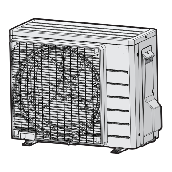
Technical data 6.4.2 Component overview: Outdoor unit a Air thermistor R1T j Service PCB b Heat exchanger k High pressure switch (only for RXP50~71L, RXP50~71M, RXP50~71N and ARXP20~35M) c Expansion valve l Discharge pipe thermistor R3T d Heat exchanger thermistor R2T m Muffler e Liquid receiver n Accumulator... -
Page 183: Field Information Report
Technical data 6.5 Field information report See next page. ATXP20~35 + FTXP20~71 + ARXP20~35 + RXP20~71 Service manual Split Comfora R32 ESIE18-01E – 2023.01... - Page 184 In case a problem occurred on the unit which could not be resolved by using the content of this service manual or in case you have a problem which could be resolved but of which the manufacturer should be notified, we advise you to contact your distributor.
- Page 185 Application information Application (house, apartment, office,…): New project or reimbursement: Heat emitters (radiators / under floor heating / fan coils /…): Hydraulic layout (simple schematic): Unit / Installation information Model name: Serial number: Installation / commissioning date: Software version hydro PCB A1P Software version hydro PCB A5P Software version user interface: Software version outdoor PCB:...
-
Page 186: Service Tools
Technical data 6.6 Service tools 1 For an overview of the available service tools, check the Daikin Business Portal (authentication required). 2 Go to the tab After-sales support on the left navigation pane and select Technical support. 3 Click the button Service tools. An overview of the available service tools for the different products is shown. -
Page 187: Field Settings
Technical data 6.7 Field settings 6.7.1 Field settings: Indoor unit To control the indoor unit fan during thermostat off in cooling 1 Press , and simultaneously. 2 Press 3 Select SU. 4 Press to confirm. 5 Press 6 Select 4. 7 Press to confirm. - Page 188 Technical data To change auto restart ON to OFF INFORMATION After power failure, the unit will automatically restart (default setting). It is possible to switch OFF auto restart. For example: after a long power failure, generators have to start‑up. As there is limited energy and the air conditioners do NOT have priority, it is recommended to switch OFF auto restart.
-
Page 189: Field Settings: Outdoor Unit
Technical data 6.7.2 Field settings: Outdoor unit To set the facility settings INFORMATION These settings are only to be used for facilities such as equipment or computer rooms and never in a residence or office with people. 1 Cut the jumper J6 on the circuit board using nippers or a similar tool to expand the operation range of the outdoor unit down to –15°C. - Page 192 ESIE18-01E 2023.01 Verantwortung für Energie und Umwelt...
Need help?
Do you have a question about the FTXP20-71L and is the answer not in the manual?
Questions and answers