Table of Contents
Advertisement
Quick Links
INSTALLER: Leave this manual with party responsible for use and operation.
OWNER: Retain this manual for future reference.
NOTICE: DO NOT discard this manual!
Models:
This appliance may be installed as an OEM
installation in manufactured home (USA
only) or mobile home and must be installed
in accordance with the manufacturer's
instructions and the Manufactured Home
Construction and Safety Standard, Title 24
CFR, Part 3280 in the United States, or the
Standard for Installation in Mobile Homes,
CAN/CSA Z240 MH Series, in Canada.
This appliance is only for use with the type(s)
of gas indicated on the rating plate. This
appliance is not convertible for use with other
gases, unless a certified kit is used.
In the Commonwealth of Massachusetts installation must be
performed by a licensed plumber or gas fitter.
See Table of Contents for location of additional Commonwealth
of Massachusetts requirements.
Installation Manual
Installation and Appliance Setup
Heat & Glo • 6000CL-IFT, 8000CL-IFT Installation Manual • 2504-980 Rev. Q • 11/21
WARNING:
FIRE OR EXPLOSION HAZARD
Failure to follow safety warnings exactly
could result in serious injury, death, or
property damage.
• DO NOT store or use gasoline or other flam-
mable vapors and liquids in the vicinity of this
or any other appliance.
• What to do if you smell gas
- DO NOT try to light any appliance.
- DO NOT touch any electrical switch. DO
NOT use any phone in your building.
- Leave the building immediately.
- Immediately call your gas supplier from
a neighbor's phone. Follow the gas sup-
plier's instructions.
- If you cannot reach your gas supplier, call
the fire department.
• Installation and service must be performed
by a qualified installer, service agency, or the
gas supplier.
DANGER
DO NOT TOUCH GLASS
NEVER ALLOW CHILDREN
A barrier designed to reduce the risk of
burns from the hot viewing glass is provided
with this appliance and must be installed for
the protection of children and other at-risk
individuals.
HOT GLASS WILL
CAUSE BURNS.
UNTIL COOLED.
TO TOUCH GLASS.
1
Advertisement
Table of Contents

Subscribe to Our Youtube Channel
Related Manuals for Heat & Glo 6000CL-IFTLP-S


Summary of Contents for Heat & Glo 6000CL-IFTLP-S
- Page 1 Installation Manual Installation and Appliance Setup INSTALLER: Leave this manual with party responsible for use and operation. OWNER: Retain this manual for future reference. NOTICE: DO NOT discard this manual! WARNING: FIRE OR EXPLOSION HAZARD Failure to follow safety warnings exactly could result in serious injury, death, or Models: property damage.
-
Page 2: Table Of Contents
Safety Alert Key: • DANGER! Indicates a hazardous situation which, if not avoided will result in death or serious injury. • WARNING! Indicates a hazardous situation which, if not avoided could result in death or serious injury. • CAUTION! Indicates a hazardous situation which, if not avoided, could result in minor or moderate injury. •... -
Page 3: Installation Standard Work Checklist
Installation Standard Work Checklist ATTENTION INSTALLER: Follow this Standard Work Checklist This standard work checklist is to be used by the installer in conjunction with, not instead of, the instructions contained in this installation manual. Customer: Date Installed: Lot/Address: Location of Fireplace: Installer: Model (circle one): 6000CL-IFT 6000CL-IFTLP... -
Page 4: Product Specific And Important Safety Information
D. High Altitude Installations NOTICE: If the heating value of the gas has been reduced, these rules do not apply. Check with your local gas utility MODELS: 6000CL-IFT-S, 6000CL-IFTLP-S, or authorities having jurisdiction. 6000CL-IFT-G, 6000CL-IFTLP-G, When installing above 2000 feet elevation: 8000CL-IFT-S, 8000CL-IFTLP-S, •... -
Page 5: Requirements For The Commonwealth Of Massachusetts
Inspection Note: The following requirements reference various The state or local gas inspector of the side wall horizon- Massachusetts and national codes not contained in this tally vented gas fueled equipment shall not approve the document. installation unless, upon inspection, the inspector ob- serves carbon monoxide detectors and signage installed I. -
Page 6: Getting Started
Getting Started A. Design and Installation Considerations B. Good Faith Wall Surface Heat & Glo direct vent gas appliances are designed to operate with all combustion air siphoned from outside of FIREPLACE OPENING TO CEILING the building and all exhaust gases expelled to the outside. 127°F No additional outside air source is required. -
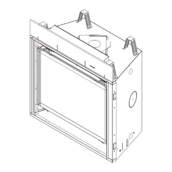
Page 7: Inspect Appliance And Components
D. Inspect Appliance and Components • Carefully remove the appliance and components from the packaging. • The vent system components and decorative doors and fronts may be shipped in separate packages. • If packaged separately, the log set and appliance grate must be installed. -
Page 8: Framing And Clearances
Framing and Clearances A. Appliance/Decorative Front Dimension Diagrams Dimensions are actual appliance dimensions. Use for reference only. For framing dimensions and clearances refer to Section 5. TOP VIEW HEAT MANAGEMENT SYSTEMS ACCESS (LEFT & RIGHT SIDES) ELECTRICAL ACCESS GAS LINE (C) L ACCESS LEFT SIDE... - Page 9 TOP VIEW HEAT MANAGEMENT SYSTEMS ACCESS (LEFT & RIGHT SIDES) ELECTRICAL ACCESS (C) L GAS LINE ACCESS LEFT SIDE RIGHT VIEW FRONT VIEW Appliance Dimensions Table Location Inches Millimeters Location Inches Millimeters 1219 11-11/16 35-1/2 43-1/8 1096 17-3/4 35-1/2 8-1/2 36-5/8 2-3/8 2-7/8...
- Page 10 FOLIO DECORATIVE FRONTS 32-7/16 23-1/8 35-13/16 1-1/2 8-1/4 32-1/8 33-9/16 6000 FOL-36 39-7/16 25-5/16 42-13/16 1-1/2 8-1/4 34-1/8 35-11/16 8000 FOL-42 1002 1087 ARCADIA DECORATIVE FRONTS 32-7/16 20-1/2 37-1/4 1-1/4 7-11/16 32-7/8 34-1/8 6000 ARC-36 39-7/16 22-7/16 44-1/4 1-1/4 7-11/16 34-13/16 36-1/16 8000...
- Page 11 HALSTON DECORATIVE FRONTS 32-7/16 21-1/4 37-1/4 1-1/4 7-1/4 32-7/8 34-1/8 6000 HAL-36 39-7/16 23-1/8 44-1/4 1-1/4 7-1/4 34-13/16 36-1/16 8000 HAL-42 1002 1124 CHATEAU DECORATIVE FRONTS 20-1/2 32-7/16 37-1/4 1-1/2 7-7/8 32-7/8 34-1/8 6000 CHA-36 22-7/16 39-7/16 44-1/8 1-1/4 7-7/8 34-13/16 36-1/16 8000...
- Page 12 CHATEAU FORGE DECORATIVE FRONTS 32-1/4 20-3/4 1-3/16 7-9/16 32-7/8 34-1/8 6000 CHAF-36 39-1/4 22-5/8 1-1/4 7-5/8 34-3/4 8000 CHAF-42 1118 GALLERIA DECORATIVE FRONTS 31-9/16 20-7/8 37-1/8 1-1/4 7-1/2 32-7/8 34-1/16 6000 GALLERIA-6 38-9/16 22-3/4 44-1/16 1-1/4 7-1/2 34-3/4 8000 GALLERIA-8 1121 Figure 3.5 Decorative Front Dimensions - Chateau Forge and Galleria Heat &...
- Page 13 CLEAN FACE DECORATIVE FRONTS 31-9/16 22-1/8 35-13/16 3-1/2 4-9/16 26-13/16 28-15/16 6000 CF-36 38-1/2 24-1/16 42-3/4 3-1/2 4-9/16 28-11/16 30-13/16 8000 CF-42 1086 IRON AGE DECORATIVE FRONTS 27-3/8 23-1/8 37-3/16 1-1/4 6-3/4 32-7/8 34-1/8 6000 FSI-36 34-3/8 25-3/16 44-3/16 1-1/4 6-3/4 34-13/16 36-1/16...
-
Page 14: Clearances To Combustibles
NOTICE: Illustrations reflect typical installations and are B. Clearances to Combustibles FOR DESIGN PURPOSES ONLY. Illustrations/diagrams When selecting a location for the appliance it is important are not drawn to scale. Actual installation may vary due to to consider the required clearances to walls. See Figure individual design preference. - Page 15 COMBUSTIBLE FLOORING MAY BE INSTALLED NEXT TO THE FRONT OF THE APPLIANCE. MINIMUM FRAMING DIMENSIONS G*** Rough Rough Rough Rough Clearance to Ceiling Models Combustible Combustible Behind Sides of Front of Opening Opening Opening Opening (Measured from top of Floor Flooring Appliance Appliance...
-
Page 16: Constructing The Appliance Chase
C. Constructing the Appliance Chase D. Floor Protection A chase is a vertical box-like structure built to enclose the Vinyl Flooring gas appliance and/or its vent system. In cooler climates Vinyl flooring is sensitive to heat. To avoid damage to the vent should be enclosed inside the chase. -
Page 17: Termination Location And Vent Information
Termination Location and Vent Information A. Vent Termination Minimum Clearances 6 in. (minimum) up to 20 in. 18 in. minimum WARNING 152 mm/508 mm 457 mm 20 in. and over 0 in. minimum Fire Risk. Gas, Wood or Fuel Oil Maintain vent clearance to combustibles as Termination Cap specified. -
Page 18: Vent Terminal Clearances
B. Vent Terminal Clearances = AREA WHERE TERMINAL IS NOT PERMITTED = AIR SUPPLY INLET = VENT TERMINAL Electrical H or i Service U.S.A. Installations: In accordance with the current ANSI Z223.1/NFPA 54, National Fuel Gas Code. Canadian Installations: In accordance with the current CSA B149.1, Natural Gas and Propane Installation Code. U.S.A. -
Page 19: Approved Pipe
C. Approved Pipe This appliance is approved for use with Hearth & Home Technologies DVP or SLP venting systems. Refer to Sec- tion 12.A for vent component information and dimensions. Only use listed decorative termination caps/shrouds with Hearth & Home Technologies approved venting systems. DO NOT mix pipe, fittings or joining methods from differ- ent manufacturers. -
Page 20: Use Of Elbows
D. Use of Elbows Diagonal runs have both vertical and horizontal vent as- pects when calculating the effects. Use the rise for the vertical aspect and the run for the horizontal aspect. See Figure 4.5. Two 45º elbows may be used in place of one 90º elbow. On 45º... -
Page 21: Measuring Standards
E. Measuring Standards Vertical and horizontal measurements listed in the vent diagrams were made using the following standards: • Pipe measurements are shown using the effective length of pipe. See Section 12.A (Figure 12.1 for DVP, Figure 12.8 for SLP) for information on effective length of pipe components. -
Page 22: Vent Diagrams
F. Vent Diagrams WARNING General Rules: Fire Risk. Explosion Risk. • SUBTRACT 3 ft. from the total H measurement for each Do NOT pack insulation or other combustibles 90º elbow installed horizontally. between ceiling firestops. • SUBTRACT 1-1/2 ft. from the total H measurement for •... - Page 23 Top Vent - Horizontal Termination One Elbow WARNING! Risk of Fire! Elbow heat shield required Note: For corner installations: A 6 inch (152 when V = 2 ft. or less. Clearances to combustibles mm) section of straight pipe may need to must be maintained.
- Page 24 Top Vent - Horizontal Termination - (continued) Two Elbows Note: For corner installations: A 6 in. (152 mm) section of straight pipe may need to be attached to the appliance before a 90º elbow, to allow the vent pipe to clear the top standoffs. 6000CL-IFT 8000CL-IFT Minimum...
- Page 25 Top Vent - Horizontal Termination - (continued) Three Elbows Min. Max. Min. Max. Elbow only 2 ft. 610 mm 0 in. 0 mm 1 ft. 305 mm 6 in. 152 mm 3 ft 914 mm 6 in. 152 mm 2 ft. 610 mm 1 ft.
- Page 26 Top Vent - Vertical Termination Flue Restrictor Instructions 1. Remove the top piece of refractory, if already installed. No Elbow See Figure 4.14. 2. Orientate and align the two pieces of the flue restrictor = 40 ft. Max. (12.4 m) as shown in Figure 4.16.
- Page 27 Top Vent - Vertical Termination (continued) ALWAYS USED WITH THE HOLES TO THE RIGHT 4 3 2 1 4 3 2 1 ALWAYS USED WITH THE FLUE RESTRICTOR SET TO 4-4 HOLES TO THE LEFT Note: If the DVP-2SL or DVP-SLP24 adapter is used with SLP pipe, you MUST subtract one number from the table in Figure 4.14.
- Page 28 Top Vent - Vertical Termination - (continued) Three Elbows Minimum Maximum Elbow only 1 ft. 305 mm 1 ft. 305 mm 6 in. 152 mm 2 ft. 610 mm 2 ft. 610 mm 1 ft. 305 mm 2 ft. 610 mm 2 ft.
- Page 29 Rear Vent - Horizontal Termination No Elbow = 16 in. (406 mm) Maximum Figure 4.19 One 45º Elbow Do not use a 45º elbow in corner installations. Use two 90º elbows instead. Figure 4.20 Heat & Glo • 6000CL-IFT, 8000CL-IFT Installation Manual • 2504-980 Rev. Q • 11/21...
- Page 30 Rear Vent - Horizontal Termination - (continued) Maximum Minimum Maximum Two Elbows Back to Back 1 ft. 305 mm 1 ft. 305 mm 2 ft. 610 mm 90º Elbows 2 ft. 610 mm 6 in. 152 mm 2 ft. 610 mm 4 ft.
- Page 31 Rear Vent - Horizontal Termination - (continued) 6000CL-IFT Three Elbows Maximum Minimum Max. Back to Back 1 ft. 305 mm 1 ft. 305 mm 2 ft. 610 mm 90º Elbows 2 ft. 610 mm 6 in. 152 mm 1.5 ft. 457 mm 3.5 ft.
- Page 32 Rear Vent - Vertical Termination Minimum Maximum One Elbow 6 in. 152 mm 2 ft. 610 mm 1 ft. 305 mm 3 ft. 914 mm 2 ft. 610 mm 5 ft. 1.5 m 3 ft. 914 mm 7 ft. 2.1 m 4 ft.
- Page 33 Rear Vent - Vertical Termination - (continued) Maximum Minimum Maximum Three Elbows 2 ft. 610 mm 6 in. 152 mm 2 ft. 4 ft. 1.2 m 3 ft. 914 mm 1 ft. 305 mm 4 ft. 1.2 m 7 ft. 2.1 m 5 ft.
-
Page 34: Vent Clearances And Framing
Vent Clearances and Framing A. Pipe Clearances to Combustibles The attached insulation has been tested and approved by Hearth & Home WARNING! Risk of Fire! Maintain air space clearance Technologies and is UL approved. to vent. DO NOT pack insulation or other combustibles: This insulation may contact the vent pipe. -
Page 35: Wall Penetration Framing/Firestops
B. Wall Penetration Framing/Firestops Combustible Wall Penetration Whenever a combustible wall is penetrated, you must frame a hole for the wall shield firestop(s). The wall shield firestop maintains minimum clearances and prevents cold air infiltration. • The opening must be framed on all four sides using the same size framing materials as those used in the wall construction. -
Page 36: Ceiling Firestop/Floor Penetration Framing
C. Ceiling Firestop/Floor Penetra- tion Framing A ceiling firestop MUST be used between floors and attics. • DVP pipe only - Frame an opening 10 in. by 10 in. (254 mm by 254 mm) whenever the vent penetrates a ceiling/floor (see ATTIC ABOVE Figure 5.4). -
Page 37: Appliance Preparation
Appliance Preparation A. Vent Collar Preparation NOTICE: Once the seal cap has been removed it CANNOT be reattached. CAUTION! Risk of Cuts, Abrasions or Flying Debris. Wear protective gloves and safety glasses during instal- lation. Sheet metal edges are sharp. NOTICE: Once appliance is set up for top or rear venting, it CANNOT be changed at a later time. - Page 38 Figure 6.6 (Generic Fireplace Shown) To attach the first section of vent pipe, make sure to use the fiberglass gasket in the manual bag to seal between the first vent component and the outer fireplace wrap. Caulk with a minimum of 300 ºF continuous exposure rating may be used to hold the part in place.
-
Page 39: Installing Optional Heat Management Systems
B. Installing Optional Heat Management Systems NOTICE: Additional clearances are required for heat management systems installations. Provisions must be made in advance to ensure fit within the framing. • Locate the heat management ports on the left and right sides of the appliance. Either one or two Heat- Zone -Gas Kits may be installed. -
Page 40: Securing And Leveling The Appliance
C. Securing and Leveling the Appliance WARNING! Risk of Fire! Prevent contact with: • Sagging or loose insulation • Insulation backing or plastic • Framing and other combustible materials Block openings into the chase to prevent entry of blown- in insulation. Make sure insulation and other materials are secured. -
Page 41: Venting And Chimneys
Venting and Chimneys from horizontal to vertical, one screw minimum should be put A. Assemble Vent Sections (DVP Pipe Only) in the outer flue at the horizontal elbow joint to prevent the Attach Vent to the Firebox Assembly elbow from rotating. Use screws no longer than 1/2 in. (13 mm). -
Page 42: Assemble Vent Sections (Slp Only)
B . Assemble Vent Sections (SLP Only) C. Assemble Slip Sections • Slide the inner flue of the slip section into the inner flue To attach the first vent component to the starting collars of the appliance: of the pipe section and the outer flue of the slip section over the outer flue of the pipe section. -
Page 43: Secure The Vent Sections
D. Secure the Vent Sections E. Disassemble Vent Sections • Vertical runs originating off the top of the appliance, with • Rotate either section (see Figure 7.10) so the seams on no offsets, must be supported every 8 ft. (2.44 m) after both pipe sections are aligned as shown in Figure 7.11. -
Page 44: Vertical Termination Requirements
NOTICE: Failure to properly caulk the roof flashing and F. Vertical Termination Requirements pipe seams could permit entry of water. Install Metal Roof Flashing • Caulk the gap between the roof flashing and the outside • See minimum vent heights for various pitched roofs diameter of the pipe. -
Page 45: Horizontal Termination Requirements
Install Vertical Termination Cap G. Horizontal Termination Requirements • Attach the vertical termination cap by sliding the inner Heat Shield Requirements for Horizontal collar of the cap into the inner flue of the pipe section Termination while placing the outer collar of the cap over the outer WARNING! Risk of Fire! To prevent overheating and fire, flue of the pipe section. - Page 46 Note: When using termination caps with factory-supplied Install Horizontal Termination Cap (DVP and heat shield attached, no additional wall shield firestop is SLP Pipe) required on the exterior side of a combustible wall. WARNING! Risk of Fire! The telescoping flue section of the termination cap MUST be used when connecting vent.
-
Page 47: Electrical Information
Electrical Information Junction Box Installation A. General Information If the box is being wired from the INSIDE of the appliance: WARNING! Risk of Shock or Explosion! DO NOT wire 110-120 VAC to the valve or to the appliance wall switch. •... - Page 48 IFT-ACM IFT-ECM FRONT PLACEMENT TAB LED CONTROLLER, IFT-ACM & IFT-ACM POWER SUPPLY Standard only on these models: 6000CL-IFT-S 6000CL-IFTLP-S 8000CL-IFT-S 8000CL-IFTLP-S Figure 8.2. Electrical Component Tray Heat & Glo • 6000CL-IFT, 8000CL-IFT Installation Manual • 2504-980 Rev. Q • 11/21...
-
Page 49: Wiring Requirements
IFT-RC150 (OPTIONAL) WIRELESS GROUND WALL SWITCH (OPTIONAL) 3 PRONG 110VAC RF MODULE CONTROL REAR ACCENT LIGHTING (X 2) 6000CL-IFT-S, 6000CL-IFTLP-S, 8000CL-IFT-S, AND 8000CL-IFTLP-S MODELS ONLY 6V DC APPLIANCE ON/OFF BATTERY PACK BRN BLK CONTROL (OPTIONAL) Figure 8.3 IntelliFire Touch Wiring Diagram... - Page 50 Wall Switch Installation for Fan (Optional) If the box is being wired to a wall mounted switch for use with a fan. See Figure 8.4: Switch Minimum 14-3 AWG • The power supply for the appliance must be brought into with Ground a switch box.
-
Page 51: Gas Information
Gas Information A. Fuel Conversion C. Gas Connection • Make sure the appliance is compatible with available gas • Refer to Section 3 for location of gas line access in types. appliance. • Conversions must be made by a qualified service •... -
Page 52: Air Shutter Setting
E. Air Shutter Setting Air shutter settings should be adjusted by a qualified ser- vice technician at the time of installation. The air shutter is set at the factory for minimum vertical vent run. Adjust air shutter for longer vertical runs. See Figure 9.1. •... -
Page 53: Finishing
Finishing A. Facing Material • Metal front faces may be covered with non-combustible materials only. FACTORY-INSTALLED NON-COMBUSTIBLE BOARD DO NOT REMOVE • Facing and/or finishing materials must not interfere with air flow through or removal of decorative fronts or access for service. -
Page 54: Mantel And Wall Projections
B. Mantel and Wall Projections Mantel Legs or Wall Projections WARNING! Risk of Fire! Comply with all minimum clear- ances as specified. Framing closer than the minimums list- INTERIOR WALL ed must be constructed entirely of noncombustible materials (i.e., steel studs, concrete board, etc.) TOP VIEW Mantels - Combustible or Painted Surfaces Note: All... -
Page 55: Decorative Fronts
C. Decorative Fronts Finishing Material: 1 Inch Thick or Less Only decorative fronts certified for use with this appliance model may be used. Contact your dealer for a list of dec- orative fronts that may be used. Once you have deter- Remove Finishing Strips. - Page 56 Finishing Material Thickness: 1-6 Inches Maximum NOTICE: Remove finishing strips before firing appliance. FINISHING STRIPS USED NON-COMBUSTIBLE FINISHING MATERIAL (Outside decorative front width) (Includes 1/8 in. opening each side of decorative front) Finishing material thickness, 1-6 inches maximum B = Top of decorative front to bottom of fireplace. D = Bottom of Finishing Material to Bottom of Fireplace 8000 Models 6000 Models...
- Page 57 Removal of Finishing Strips Finishing Material Thickness: 0-6 Inches Maximum NOTICE: Remove finishing strips before firing appliance. Remove glass frame assembly to access finishing strip screws. NOTICE: Remove finishing strips before firing appliance. FINISHING STRIP NOT USED (See Figure 10.9 for removal instructions) NON-COMBUSTIBLE FINISHING MATERIAL...
-
Page 58: Appliance Setup
11 11 Appliance Setup C. Clean the Appliance A. Remove Fixed Glass Assembly Clean/vacuum any sawdust that may have accumulated WARNING! Risk of Asphyxiation! Handle fixed glass inside the firebox or underneath in the control cavity. assembly with care. Inspect the gasket to ensure it is undamaged and inspect the glass for cracks, chips or scratches. -
Page 59: Install The Fiber Refractory
E. Install the Fiber Refractory 6000CL-IFT-S 8000CL-IFT-S REFRACTORY REFRACTORY 6000CL-IFTLP-S 8000CL-IFTLP-S FOOT FOOT NOTCH NOTCH CAUTION! Risk of Cuts, Abrasions or Flying Debris. Wear protective gloves and safety glasses during instal- lation. LOWER LOWER CAUTION! Refractory is fragile. Handle with care. - Page 60 Step 4. Top Refractory Installation Step 3. Left Refractory Installation 7. Using both hands, hold the top refractory panel with 6. Steps for installation of left refractory side are the same the brick pattern facing down. as right side. Repeat the same procedure as Step 2. 8.
-
Page 61: Black Glass Refractory Installation
6. Bend side refractory tab over glass panel. See Fig- F. Black Glass Refractory Installation ure 3. 6000CL-IFT-G 8000CL-IFT-G 7. Install side insulation board on opposite side and re- 6000CL-IFTLP-G 8000CL-IFTLP-G peat steps 4-6 for other side. 1. Locate the black glass refractory components which are shipped inside the appliance. -
Page 62: Ember Placement
G. Ember Placement WARNING! Risk of Explosion! Follow ember placement instructions in manual. DO NOT completely block burner ports with ember material. Replace ember material annu- ally. Improperly placed embers interfere with proper burner operation. Ember material is shipped with this gas appliance. To place the ember material: •... -
Page 63: Install The Log Assembly
H. Install the Log Assembly LOG PLACEMENT INSTRUCTIONS Log Set Assembly: LOGS-6CL Models: 6000CL-IPI-S, 6000CL-IPILP-S, 6000CL-IPI-T, 6000CL-IPILP-T 6000CL-IFT-S, 6000CL-IFTLP-S, 6000CL-IFT-G, 6000CL-IFTLP-G LOCATING HOLES FIBER BURNER TOP LOG PLACEMENT TABS LOG PLACEMENT TABS TAB BENT IN = NG BURNER SHIELD PILOT COVER... - Page 64 NOSE NOSE RIGHT GRATE TINE RIGHT GRATE TINE Figure 7 Figure 8 Log #3 (SRV2164-703): Mate the slot located on the bottom of Log #3 with the right log placement tab on top of Log #1. After slot and tab have been fitted together, mate the groove located on the bottom of Log #3 with the horizontal grate bar and slide Log # 3 toward the right until it rests against the far right grate tine (see Figure 7).
- Page 65 Log Set Assembly: LOGS-8CL LOG PLACEMENT INSTRUCTIONS Models: 8000CL-IPI-S, 8000CL-IPILP-S, 8000CL-IPI-T, 8000CL-IPILP-T 8000CL-IFT-S, 8000CL-IFTLP-S, 8000CL-IFT-G, 8000CL-IFTLP-G LOCATING HOLES FIBER BURNER TOP LOG PLACEMENT INDENTATIONS LOG PLACEMENT INDENTATIONS TAB BENT IN = NG LOG PLACEMENT TABS LOG PLACEMENT TABS BURNER SHIELD PILOT COVER BURNER ASSEMBLY TAB NOT BENT = LP...
- Page 66 RIGHT GRATE TINE RIGHT GRATE TINE HORIZONTAL GRATE BAR HORIZONTAL GRATE BAR LOG #4 CONTACTS LOG #2 LOG #4 CONTACTS LOG #2 Figure 7 Figure 8 Log #3 (SRV2168-703): Mate the slot located on the bottom of Log #3 with the right log placement tab on top of Log #1. After slot and tab have been fitted together, mate the groove located on the bottom of Log #3 with the horizontal grate bar and far right grate tine.
-
Page 67: Intellifire Touch Control System Setup
I. IntelliFire Touch ® Control System Setup J. Install Fixed Glass Assembly • Detailed instructions for electrical wiring and connec- WARNING! Risk of Asphyxiation! Handle fixed glass tions are provided in Section 8. assembly with care. Inspect the gasket to ensure it is undamaged and inspect the glass for cracks, chips or •... -
Page 68: Reference Materials
Reference Materials A. Vent Components Diagrams Effective Length Pipe Inches Millimeters DVP4 10-1/2 in. (267 mm) 45 ° Effective DVP6 Height/Length DVP12 DVP24 4-7/8 in. (124 mm) DVP36 10-7/8 in. DVP48 1219 (276 mm) DVP Pipe (see chart) DVP6A 3 to 6 76 to 152 DVP45 (45º... - Page 69 A. Vent Components Diagrams (continued) Note: Heat shields MUST overlap by a minimum of 1-1/2 in. (38 mm). The heat shield is designed to be used on a wall 4 in. to 7-1/4 in. (102 mm to 184 mm) thick. If wall thickness is less than 4 in. (102 mm) the existing heat shields must be field trimmed.
- Page 70 A. Vent Components Diagrams (continued) 31 in. (787 mm) 13-1/4 in. (337 mm) 24-5/8 in. (625 mm) 27-1/2 in. 24-5/8 in. (699 mm) (625 mm) 13-1/4 in. (337 mm) RF12 Roof Flashing Roof Flashing 11-7/8 in. 5 in. (302 mm) (127 mm) 13-7/8 in.
- Page 71 A. Vent Components Diagrams (continued) 7-3/8 in. (187 mm) 1-1/2 in. (38 mm) 12 in. 305 mm 14 in. 17-3/4 in. (356 mm) (451 mm) 7-1/4 in. (184 mm) 6 in. 12-1/2 in. 152 mm (318 mm) 5-1/4 in. 12 in. (133 mm) (305 mm) DVP-TVHW...
- Page 72 A. Vent Components Diagrams (continued) 8-1/8 in. 13 in. (206 mm) (330 mm) Effective Length 5-1/2 in. 8-3/8 in. 5-3/4 to 8-3/8 in. 140 mm 213 mm 146 to 213 mm 3° 87° 15 in. (381 mm) 10-1/2 in. 267 mm 10-7/8 in.
- Page 73 A. Vent Components Diagrams (continued) TOP VIEW Required Wire Harness and PVV-SLEEVE Lengths Available Part Number 10 ft. PV Wire Harness PVI-WH10 20 ft. PV Wire Harness PVI-WH20 40 ft. PV Wire Harness PVI-WH40 13-11/16 IN. 60 ft. PV Wire Harness PVI-WH60 80 ft.
- Page 74 A. Vent Components Diagrams (continued) Optional Wire Harness 13-5/8 IN. 346 mm DESCRIPTION PART NUMBER EFFECTIVE LENGTH 32 IN. (813 mm) MIN. 10 FT PV Wire Harness PVI-WH10 35 IN. (889 mm) MAX. 20 FT PV Wire Harness PVI-WH20 40 FT PV Wire Harness PVI-WH40 12-1/2 IN.
- Page 75 A. Vent Components Diagrams (continued) Top View 6-1/4 IN. 159 mm 1-1/2 IN. 38 mm Front View Side View 2-1/4 IN. 15-1/2 IN. 57 mm 394 mm 4-3/4 IN. 121 mm 8 IN. 14 IN. 9-1/2 IN. 203 mm 356 mm 241 mm 5-1/4 IN.
- Page 76 A. Vent Components Diagrams (continued) 6-1/2 in. 165 mm 6-1/2 in. 165 mm 6-1/2 in. 165 mm 8-3/4 in. 9-1/4 in. 222 mm 6 in. 235 mm 152 mm 6-5/8 in. 168 mm 6-5/8 in. SLP45 168 mm 45° Elbow 9-7/8 in.
- Page 77 A. Vent Components Diagrams (continued) Note: Heat shields MUST overlap by a minimum of 1-1/2 in. (38 mm). The heat shield is designed to be used on a wall 4 in. to 7-1/4 in. (102 mm to 184 mm) thick. If wall thickness is less than 4 in. (102 mm) the existing heat shields must be field trimmed.
- Page 78 A. Vent Components Diagrams (continued) 12 in. 305 mm 14 in. 13 in. 356 mm 330 mm 12-1/2 in. 1-5/16 in. 318 mm 10-9/16 in. 13 in. 34 mm 269 mm 330 mm SLP-CCS-BK SLP-DCF-BK SLP-TVHW Cathedral Ceiling Ceiling Firestop Vertical Support Box-Black Black...
-
Page 79: Accessories
B. Accessories Remote Controls, Wall Controls and Wall Switches Follow the instructions supplied with the control installed to operate your fireplace: For safety: • Install a switch lock or a wall/remote control with child protection lockout feature. • Keep remote controls out of reach of children. See your dealer if you have questions.
Need help?
Do you have a question about the 6000CL-IFTLP-S and is the answer not in the manual?
Questions and answers