
Related Manuals for CTC Union JB320 Series


Summary of Contents for CTC Union JB320 Series
- Page 1 JB320 Series Switch Box JB320 Series Switch Box 4-12 Channel 4-12 Channel Product Manual Product Manual...
-
Page 2: Table Of Contents
Table of Contents • Introduction . . . . . . . . . . . . . . . . . . . . . . . . . . . . . . . . . . . . . . . . . . . . . . . . . . . . . . . . . . . . . . . . . . .3 •... -
Page 3: Introduction
CTC switch box solutions allow for the monitoring of remotely mounted vibration sensors, which would otherwise be restricted to human access due to safety considerations . JB320 Series Switch Box Overview: 4-12 channel boxes, stainless steel enclosure The JB320 Dual Output Switch Box is a common cable termination point for... -
Page 4: Product Dimensions
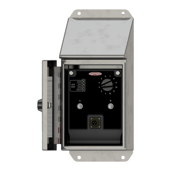
Product Dimensions Front View Side View Figure 1. Dimensions Bias Indicator Switch Light Measurement Location Card Data Collector Access (BNC) Ch . B Data Collector Access (BNC) Ch . A Input Terminal Strip Options Quick Screw Data Collector Connect Terminal Access (3 pin) Option Option... -
Page 5: Mounting Instructions
Mounting Instructions Molded mounting brackets are included on the enclosure . Wall anchoring screws are not included . Mounting Vibration Brackets Switch Box 0 .31 in ./7 .95 mm (Rear View) Figure 3. Mounting Bracket Placement... -
Page 6: Conduit Entry
Conduit Entry If you have purchased a enclosure without cable entries provided, you should add your own entry prior to mounting the switch box . CTC does not recommend putting holes in the top of enclosure as it will cause restricted access to the wire termination connection points and also allow possible moisture ingress . -
Page 7: Grounding
Grounding Ensure the shield ground wire on JB320 Series Switch Boxes is grounded to earth ground . A. Mounting to Earth Ground When mounting JB320 Series Switch boxes to earth ground (such as an I-Beam), no additional steps are necessary, as the enclosure is grounded internally . - Page 8 Grounding B. Mounting to non-grounded structure When mounting the switch box to a non-grounded structure, ensure the shield ground wire or customer supplied ground wire is tied to a source of earth ground . Figure 6. Ground Wire Placement...
-
Page 9: Sensor Installation
Sensor Installation Installation of sensors/signal input cable Feed blunt cut end through the cable entry at the bottom of the enclosure . Note: it is recommended that cables are marked on both ends . For cord grip cable entry, take off the cord grip cover with bushing and run cable through it then into the enclosure, hand tighten cord grip cover to base to prevent damage of cord grip . - Page 10 Sensor Installation Locate the appropriate plug (identified by channel number), remove it, and install the wires using a small flathead screwdriver . Depress selected position button to open terminal for respective wire . Push plug back into location . Refer to the below chart for the correct orientation, based on application DUAL OUTPUT - VIB/TEMP SENSOR #1...
- Page 11 Sensor Installation Note: If your application requires continuous output, the wiring configuration for the JB320 is slightly modified . INPUT #1 INPUT #2 INPUT #3 INPUT #4 DUAL OUTPUT - VIB/TEMP VIB (+) SOCKET A RED WIRE SOCKET B BLACK WIRE COMMON Inputs TEMP (+)
-
Page 12: Post Installation Testing
Post Installation Testing The TM1018 Accelerometer Verification Meter can be used to verify cable conductivity, sensor location and proper wiring connections . The Verification Meter will indicate if the sensor, cable and/or junction box is in working condition . It will also confirm bias voltage of the accelerometer, which will inform you of the operation of the internal accelerometer amplifier . -
Page 13: Maintenance
Post Installation Testing The following LED Readout indicates the circuit integrity: Green LED: Normal . Indicates proper connection and an output bias will be given, indicating the health of the sensor (4 – 16 V indicates a healthy accelerometer) . Yellow LED: Open Circuit . -
Page 14: Warranty & Refund
Warranty & Refund Warranty All CTC products are backed by our unconditional lifetime warranty . If any CTC product should ever fail, we will repair or replace it at no charge . Refund All stock products qualify for a full refund if returned in new condition within 90 days of shipment .
Need help?
Do you have a question about the JB320 Series and is the answer not in the manual?
Questions and answers