
Subscribe to Our Youtube Channel
Related Manuals for EWM Taurus 400 Basic TDG


Summary of Contents for EWM Taurus 400 Basic TDG
- Page 1 Operating instructions Welding machine Taurus 400 Basic TDG 099-005446-EW501 Observe additional system documents! 22.02.2017...
- Page 2 +49 2680 181-0. A list of authorised sales partners can be found at www.ewm-group.com. Liability relating to the operation of this equipment is restricted solely to the function of the equipment.
-
Page 3: Table Of Contents
Contents Notes on the use of these operating instructions Contents 1 Contents ..............................3 2 For your safety ............................5 Notes on the use of these operating instructions ................5 2.1.1 Explanation of icons ....................... 6 Part of the complete documentation ....................7 Safety instructions .......................... - Page 4 Checklist for rectifying faults ......................38 Error messages (power source) ....................39 Resetting welding parameters to the factory settings ..............40 8 Technical data............................41 Taurus 400 Basic TDG ......................... 41 9 Accessories ............................42 System components ........................42 9.1.1 Wire feed unit ........................
-
Page 5: For Your Safety
For your safety Notes on the use of these operating instructions For your safety Notes on the use of these operating instructions DANGER Working or operating procedures which must be closely observed to prevent imminent serious and even fatal injuries. •... -
Page 6: Explanation Of Icons
For your safety Notes on the use of these operating instructions 2.1.1 Explanation of icons Symbol Description Symbol Description Indicates technical aspects which the Activate and release/tap/tip user must observe. Switch off machine Release Switch on machine Press and keep pressed Switch Wrong Turn... -
Page 7: Part Of The Complete Documentation
For your safety Part of the complete documentation Part of the complete documentation These operating instructions are part of the complete documentation and valid only in combination with all other parts of these instructions! Read and observe the operating instructions for all system components, especially the safety instructions! The illustration shows a general example of a welding system. - Page 8 For your safety Safety instructions WARNING Hazard when interconnecting multiple power sources! If a number of power sources are to be connected in parallel or in series, only a technical specialist may interconnect the sources as per standard IEC 60974-9:2010: Installation and use and German Accident Prevention Regulation BVG D1 (formerly VBG 15) or country-specific regulations.
- Page 9 For your safety Safety instructions CAUTION Smoke and gases! Smoke and gases can lead to breathing difficulties and poisoning. In addition, solvent vapour (chlorinated hydrocarbon) may be converted into poisonous phosgene due to the ultraviolet radiation of the arc! • Ensure that there is sufficient fresh air! •...
-
Page 10: Transport And Installation
For your safety Transport and installation CAUTION According to IEC 60974-10, welding machines are divided into two classes of electromagnetic compatibility (the EMC class can be found in the Technical data) > see 8 chapter: Class A machines are not intended for use in residential areas where the power supply comes from the low-voltage public mains network. - Page 11 For your safety Transport and installation The units are designed for operation in an upright position! Operation in non-permissible positions can cause equipment damage. • Only transport and operate in an upright position! Accessory components and the power source itself can be damaged by incorrect connection! •...
-
Page 12: Intended Use
In case of unauthorised changes, improper repairs, non-compliance with specified deadlines for "Arc Welding Equipment – Inspection and Testing during Operation", and/or prohibited modifications which have not been explicitly authorised by EWM, this declaration shall be voided. An original document of the specific declaration of conformity is included with every product. -
Page 13: Calibration/Validation
Intended use Documents which also apply 3.2.5 Calibration/Validation We hereby confirm that this machine has been tested using calibrated measuring equipment, as stipulated in IEC/EN 60974, ISO/EN 17662, EN 50504, and complies with the admissible tolerances. Recommended calibration interval: 12 months 099-005446-EW501 22.02.2017... -
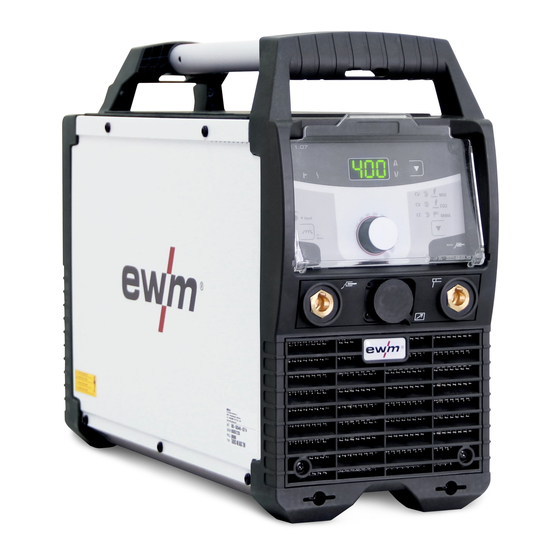
Page 14: Machine Description - Quick Overview
Machine description – quick overview Front view Machine description – quick overview Front view Figure 4-1 Item Symbol Description Transport bar Carrying strap > see 5.1.4 chapter Protective cap Connection socket, “+” welding current How to connect the accessories depends on the welding procedure. Please observe the connection description for the corresponding welding procedure >... -
Page 15: Rear View
Machine description – quick overview Rear view Rear view Figure 4-2 Item Symbol Description Cable holder Main switch, machine on/off Cooling air outlet Key button, automatic cutout Wire feed motor supply voltage fuse press to reset a triggered fuse Mains connection cable > see 5.1.9 chapter 099-005446-EW501 22.02.2017... -
Page 16: Machine Control - Operating Elements
Machine description – quick overview Machine control – Operating elements Machine control – Operating elements The setting ranges for the parameter values are summarised in the Parameter overview section > see 10.1 chapter. Figure 4-3 Item Symbol Description Collective interference signal light For error messages, >... -
Page 17: Design And Function
Design and function Transport and installation Design and function WARNING Risk of injury from electric shock! Contact with live parts, e.g. welding current sockets, is potentially fatal! • Follow safety instructions on the opening pages of the operating instructions. • Commissioning may only be carried out by persons who have the relevant expertise of working with arc welding machines! •... -
Page 18: Workpiece Lead, General
Design and function Transport and installation 5.1.3 Workpiece lead, general CAUTION Risk of burning due to incorrect welding current connection! If the welding current plugs (machine connections) are not locked or if the workpiece connection is contaminated (paint, corrosion), these connections and leads can heat up and cause burns when touched! •... -
Page 19: Cable Strap
Design and function Transport and installation 5.1.5 Cable strap In the delivery state, the machine has a cable strap for easy and orderly transport of earth lead, welding torch, electrode holder etc. The following figure shows the fastened strap and how the components can be secured. -
Page 20: Assembly
Design and function Transport and installation 5.1.6.1 Assembly Figure 5-3 5.1.6.2 Application Figure 5-4 099-005446-EW501 22.02.2017... -
Page 21: Protective Flap, Welding Machine Control
Design and function Transport and installation 5.1.7 Protective flap, welding machine control 5.1.7.1 Deinstallation/Installation Figure 5-5 Item Symbol Description Seating hole for mounting nipple Mounting nipple, protective cap Protective cap • Remove the protective cap by gently pressing from the side while simultaneously pulling. To attach, insert and snap into place. -
Page 22: Notes On The Installation Of Welding Current Leads
Design and function Transport and installation 5.1.8 Notes on the installation of welding current leads Incorrectly installed welding current leads can cause faults in the arc (flickering). Lay the workpiece lead and hose package of power sources without HF igniter (MIG/MAG) for as long and as close as possible in parallel. -
Page 23: Stray Welding Currents
Design and function Transport and installation 5.1.8.1 Stray welding currents WARNING Risk of injury due to stray welding currents! Stray welding currents can destroy protective earth conductors, damage machines and electronic devices and cause overheating of components, leading to fire. •... -
Page 24: Welding Data Display
Design and function Welding data display Figure 5-10 Legend Item Designation Colour code Outer conductor 1 brown Outer conductor 2 black Outer conductor 3 grey Neutral conductor blue Protective conductor green-yellow • Insert mains plug of the switched-off machine into the appropriate socket. Welding data display All relevant welding parameters with their values are shown depending on the welding procedure selected and the associated functions. -
Page 25: Mig/Mag Welding
Design and function MIG/MAG welding MIG/MAG welding 5.3.1 Connecting the intermediate hose package to the power source Figure 5-11 Item Symbol Description Wire feed unit Intermediate hose package 19-pole connection socket (analogue) Wire feed unit control lead connection Connection socket, welding current "+" Welding current connection on wire feed unit •... - Page 26 Design and function MIG/MAG welding Figure 5-12 If you cannot adjust the welding voltage, configuration parameter has to be set to > see 5.7 chapter. 099-005446-EW501 22.02.2017...
-
Page 27: Mig/Mag Functional Sequences / Operating Modes
Design and function MIG/MAG welding 5.3.3 MIG/MAG functional sequences / operating modes 5.3.3.1 Explanation of signs and functions Symbol Meaning Press torch trigger Release torch trigger Tap torch trigger (press briefly and release) Shielding gas flowing Welding output Wire electrode is being conveyed Wire creep Wire burn-back Gas pre-flows... - Page 28 Design and function MIG/MAG welding Non-latched mode Figure 5-13 Step 1 • Press and hold torch trigger. • Shielding gas is expelled (gas pre-flows). • Wire feed motor runs at “creep speed”. • Arc ignites after the wire electrode makes contact with the workpiece; welding current flows. •...
-
Page 29: Mma Welding
Design and function MMA welding Latched mode Figure 5-14 Step 1 • Press and hold torch trigger • Shielding gas is expelled (gas pre-flows) • Wire feed motor runs at “creep speed”. • Arc ignites after the wire electrode makes contact with the workpiece; welding current flows. •... -
Page 30: Connecting The Electrode Holder And Workpiece Lead
Design and function MMA welding 5.4.1 Connecting the electrode holder and workpiece lead Polarity depends on the instructions from the electrode manufacturer given on the electrode packaging. Figure 5-15 Item Symbol Description Electrode holder Connection socket for "+" welding current Electrode holder or workpiece lead connection Workpiece Connection socket, “-”... -
Page 31: Arcforce
Design and function MMA welding 5.4.2.1 Arcforce During the welding process, arcforce prevents the electrode sticking in the weld pool with increases in current. This makes it easier to weld large-drop melting electrode types at low current strengths with a short arc in particular. -
Page 32: Expert Menu (Mma)
Design and function Remote control 5.4.4 Expert menu (MMA) The Expert menu has adjustable parameters stored that don’t require regular setting. The number of parameters shown may be limited, e.g. if a function is deactivated. The setting ranges for the parameter values are summarised in the Parameter overview section >... -
Page 33: Power-Saving Mode (Standby)
Design and function Power-saving mode (Standby) Power-saving mode (Standby) You can activate the power-saving mode by either pressing the push-button > see 4.3 chapter for a prolonged time or by setting a parameter in the machine configuration menu (time-controlled power- saving mode ) >... - Page 34 Design and function Machine configuration menu Display Setting/selection Exit the menu Exit Machine configuration Settings for machine functions and parameter display Time-based power-saving mode > see 5.6 chapter 5 min.–60 min. = Time to activation of power-saving mode in case of inactivity. ------- inactivated Current display switching (MMA) ------- Actual value display...
-
Page 35: Maintenance, Care And Disposal
Maintenance, care and disposal General Maintenance, care and disposal General DANGER Incorrect maintenance and testing! The machine may be cleaned, repaired and tested by skilled and qualified personnel only. A qualified person is one who, due to their training, knowledge and experience, can detect any hazards and possible consequential damage when checking the machine, and can take the necessary safety measures. -
Page 36: Daily Maintenance Tasks
For more information refer to the "Warranty registration" brochure supplied and our information regarding warranty, maintenance and testing at www.ewm-group.com! A periodic test according to IEC 60974-4 "Periodic inspection and test" has to be carried out. In addition to the regulations on testing given here, the relevant local laws and regulations must also be observed. -
Page 37: Disposing Of Equipment
In addition to this, returns are also possible throughout Europe via EWM sales partners. Meeting the requirements of RoHS We, EWM AG in Mündersbach, Germany, hereby confirm that all products which we supply to you and that are subject to the RoHS directive comply with RoHS requirements (also see applicable EC directives on the Declaration of Conformity on your machine). -
Page 38: Rectifying Faults
Rectifying faults Checklist for rectifying faults Rectifying faults All products are subject to rigorous production checks and final checks. If, despite this, something fails to work at any time, please check the product using the following flowchart. If none of the fault rectification procedures described leads to the correct functioning of the product, please inform your authorised dealer. -
Page 39: Error Messages (Power Source)
Rectifying faults Error messages (power source) Error messages (power source) A welding machine error is indicated by an error code being displayed (see table) on the display on the machine control. In the event of a machine error, the power unit is shut down. The display of possible error numbers depends on the machine version (interfaces/functions). -
Page 40: Resetting Welding Parameters To The Factory Settings
Rectifying faults Resetting welding parameters to the factory settings Resetting welding parameters to the factory settings All customised welding parameters that are stored will be replaced by the factory settings. RESET Figure 7-1 Display Setting/selection Calibration The machine will be calibrated for approx 2 seconds each time it is switched on. Initialising Keep the push-button pressed until "InI"... -
Page 41: Technical Data
Technical data Taurus 400 Basic TDG Technical data Performance specifications and guarantee only in connection with original spare and replacement parts! Taurus 400 Basic TDG Setting range MIG/MAG Welding current 10 A to 400 A Welding voltage 14.5 V to 34 V 20.4 V to 36 V... -
Page 42: Accessories
Accessories System components Accessories Performance-dependent accessories like torches, workpiece leads, electrode holders or intermediate hose packages are available from your authorised dealer. System components 9.1.1 Wire feed unit Type Designation Item no. Taurus drive 4L Basic Wire feeder 090-005447-00502 Options Type Designation Item no. -
Page 43: Parameter Overview - Setting Information
Appendix A Parameter overview – setting information Appendix A Parameter overview – setting information 10.1 Parameters/function Setting range MIG/MAG Welding voltage 49,9 Dynamic correction Main current Arcforce correction Hot start current Hot start time 20,0 Arc length restriction Basic parameters (independent of procedure) Power-saving mode active Exit menu Machine configuration... -
Page 44: Overview Of Ewm Branches
Appendix B Overview of EWM branches Appendix B 11.1 Overview of EWM branches 099-005446-EW501 22.02.2017...
Need help?
Do you have a question about the Taurus 400 Basic TDG and is the answer not in the manual?
Questions and answers